 2019, Vol. 37
Institute of Oceanology, Chinese Academy of Sciences
Article Information
- LIU Qingjun, SUN Tianting, WANG Dengting, WEI Zhangping
- Wave uplift force on horizontal panels: a laboratory study
- Journal of Oceanology and Limnology, 37(6): 1899-1911
- http://dx.doi.org/10.1007/s00343-019-8292-9
Article History
- Received Oct. 15, 2018
- accepted in principle Dec. 16, 2018
- accepted for publication Feb. 20, 2019


2 College of Harbour Coastal and Offshore Engineering, Hohai University, Nanjing 210098, China;
3 Key Laboratory of Port, Waterway & Sedimentation Engineering of MOT, Nanjing 210029, China;
4 Department of Civil Engineering, Johns Hopkins University, Baltimore, MD 21218, USA
Wave uplift force on horizontal panels has a direct influence on the safety of coastal and marine structures, such as piers, bridges, and offshore platforms. There has been a considerable amount of research on damages to wharfs, bridge deck, and platforms (Broughton et al., 1988; Bea et al., 1999; Iemura et al., 2005; Jin and Meng, 2011; Hayatdavoodi and Ertekin, 2016; Wei and Dalrymple, 2016). Although bridge decks, dock panels, and offshore platforms have some differences in the structural form, e.g., the existence of cross beams, longitudinal beams, and pile caps, they all have a horizontal panel. Therefore, the mechanism of wave uplift forces on these structures is similar in nature. This study aims to understand the impact of a complex wave force on horizontal panels in a series of laboratory experiments.
The early work of wave uplift force on panels began with the study of wave impact pressure on platforms or plates (French, 1969; Wang, 1970; Suchithra and Koola, 1995). Those studies suggest that the pressure acting on the bottom of the horizontal panel is composed of two major parts: one is the rapidly changing impact pressure, and the other is the slowly varying pressure. The rapidly impact pressure is large in magnitude and short in duration. The slowly varying pressure is relatively small in magnitude and long in duration.
Although the wave uplift force on horizontal panels is closely related to the impact pressure, it is insufficient to determine the uplift force by using the pressure alone. Zhou et al. (2004) showed that the maximum total uplift forces do not necessarily occur at the same instant with the maximum impact pressure. Bradner et al. (2011) found that the large amplitude spike in pressure measurements had a little effect on wave uplift forces. Therefore, the total force of the structure should be measured precisely but estimated indirectly by the impact pressure. In recent years, many experimental studies have been carried out to directly measure wave force on horizontal panels (Isaacson and Bhat, 1996; Tirindelli et al., 2004; Cuomo et al., 2007; Murali et al., 2009; Seiffert et al., 2014; Hayatdavoodi et al., 2015; Park et al., 2017).
Isaacson and Bhat (1996) suggested that the wave uplift force on the panels is composed of the impact force, the drag force, and the buoyancy. Through the physical experiment by using regular waves, the timevarying wave uplift force was studied. Equation 1 is the empirical formula of the uplift force given by Isaacson and Bhat (1996).
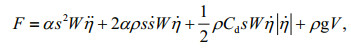 (1)
(1)where F is the wave uplift force for regular waves; α is an empirically added mass factor; s is the wet length of panels; 


Tirindelli et al. (2004) conducted a 1:25 laboratory experiment, and analyzed the wave uplift force on three types of panel structures. Based on the experiment data, they further proposed an empirical formula to estimate the quasi-static wave uplift force on the panel,
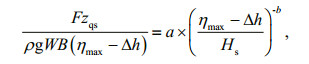 (2)
(2)where Fzqs is the quasi-static wave uplift force; Hs is the significant wave height; B is the panel width along the direction of wave propagation; ηmax is the maximum height of wave crest above the still water level (SWL); Δh is the clearance between the subsurface of the panel and the SWL; a, b are empirical coefficients related to the structural form of the panels and the location of the computational domain, respectively.
Cuomo et al. (2007) analyzed the experimental data and proposed an empirical formula to estimate the wave uplift force on the panels as follows,
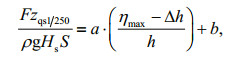 (3)
(3)where Fzqs1/250 is the quasi-static wave uplift force (at 1/250 level); S is the area of the element exposed to wave action; h is the water depth.
Murali et al. (2009) proposed an empirical formula of wave uplift force on horizontal panels in wave tank experiments. The wave uplift force formula under regular waves is given as:
 (4)
(4)where L is the wave length.
Although the aforementioned formulas could help us estimate the magnitude of wave uplift force on panels, a few issue remains. For instance, Eq.1 by Isaacson and Bhat (1996) involves time derivative terms, thus the process of solving this formula is complicated. Equation 2 by Tirindelli et al. (2004) and Eq.3 by Cuomo et al. (2007) have a simple structural form but they consider the estimation of only wave uplift force on a small specific location of the panel, and the error is obvious when estimating wave uplift force on the whole panel, especially with the large panel width. Equation 4 by Murali et al. (2009) is a simple fitting formula based on experimental data, but the physical mechanism of Eq.4 is not clear.
To address those shortcomings, we conduct a laboratory experiment on regular waves affecting horizontal panels and analyze the influence of wave height, wave length, clearance, panel width, and wave steepness on the wave uplift force. Based on the laboratory experiment, we further propose a new empirical formula to estimate wave uplift force on horizontal panels. The new empirical formula is convenient to estimate and has clear physical meanings.
This paper is organized as follows. Section 2 introduces the laboratory experiment setup and further verifies the quality of laboratory measurements through repeated runs. Section 3 analyzes the experimental results by examining the relationship between the wave uplift force F and individual variables including the wave height H, the wave period T or the wave length L, the clearance Δh, and the panel width B. In Section 4, we first carry out dimensionless analysis of the wave uplift force F/ (ρgHS) with respect to the relative clearance (ηmax–Δh)/H, the wave steepness H/L, and the relative panel width B/L, and then we propose an empirical formula based on our dimensionless analysis. Section 5 compares our empirical formula with two existing formulas reported in the literature. Finally, our major findings are summarized in Section 6.
2 LABORATORY EXPERIMENT 2.1 Instruments and equipmentThe laboratory experiment was conducted in the long wave flume of Nanjing Hydraulic Research Institute (NHRI). Figure 1 shows the sketch of a laboratory experiment setup. The flume is 175 m long, 1.5 m high and 1.2 m wide. To reduce the effects of re-reflected waves, a baffle plate 40 m long is mounted in the flume to separate the experimental section into two subsections. The width of each subsection is 0.6 m, and one of the sub-section is used to conduct the present experiment. The flume is equipped with mild slopes for dissipating waves at both ends. A piston-type wave paddle is placed at the left side of the wave flume. A horizontal panel model is located at 50 m away from the wave paddle. A capacitive-type wave gauge is placed at 0.1 m in the waveward direction of the panel to measure the wave profile, and four load cells are used to measure uplift forces. The load cell has a range of 0 to 300 N and measurement accuracy of 0.5%F.S.

|
| Fig.1 Sketch of laboratory experiment setup Top: the side view; bottom: the top view. |
Previous studies have pointed out that the panel width B along the direction of wave propagation is an important factor that affects the wave uplift force on horizontal panels (Isaacson and Bhat, 1996; Murali et al., 2009). However, those studies considered a single panel width only. As a result, they could not show the variation of wave uplift force with respect to the change of panel width. To address this issue in a thorough way, we considered three different sizes of panels in the width B at 0.5, 1.0, and 1.5 m. For the three panels, the panel length W perpendicular to the direction of wave propagation is equal to the flume width (0.6 m), as shown in the top view of Fig. 1.
The laboratory model panel is placed above the SWL by a set of the fixed trestle. The horizontal panel is connected with the fixed trestle through the vertical rod load cell. The distance between the model panel and the SWL could be adjusted to examine the influence of the clearance Δh on the wave uplift force, as shown in the side view of Fig. 1.
This study investigates the interaction between regular waves and horizontal panels. The water depth in the wave flume is 0.4 m, the wave height ranges from 0.047 to 0.147 m, and the wave period ranges from 1.0 to 3.0 s. Three different clearances of the panel over the SWL are considered, i.e., Δh=0.01, 0.03, and 0.05 m, respectively.
The whole experiment is divided into two steps. The first step is to calibrate incident wave conditions. At this stage, the horizontal panel is not placed inside the flume, and only a wave gauge is placed at the working section to measure wave parameters. The calibration of wave generation should not be considered successful until the measured wave height and wave period are within a certain range of the target values (error=(εm–εt)/εt×100%, where εm indicates the measured wave height and wave period, and εt indicates the target values, the error is set to be within 5%). We saved the input parameters associated with the calibrated wave conditions and then we could regenerate the same waves with those parameters at a later stage. At the second step, the horizontal panel properly is installed, and waves are generated by reusing the calibrated input parameters in the first step. After the interaction of the wave and the structure is relatively stable, we started to record the wave uplift force on the panel. In the test, the data sampling frequency was 100 Hz, and there are about 10 waves in each run. Finally, 100 data sets were collected in this study.
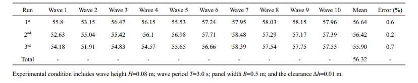
2.3 Repeatability verificationTo ensure the quality of the laboratory measurement, it is necessary to verify the repeatability of the wave condition and the corresponding wave uplift force on the panel. Here we present a selected trial, and its experimental condition includes wave height H=0.08 m, wave period T=3.0 s, panel width B=0.5 m, and the clearance Δh=0.01 m.
First, the repeatability of the wave height and wave period is verified. The time-series free surface profiles at wave gauge that is 0.1 m waveward of the panel are shown in Fig. 2a. In general, the repeatability of the wave height and wave period are very good among three runs. The wave height and wave period are stable in each run, with the averaged wave height of 0.08 m, and the average wave period of 3.0 s. The maximum wave height is 0.081 m, and the minimum wave height is 0.078 m, so the maximum error of wave height is 2.5%.

|
| Fig.2 Repeatability verification of laboratory wave generation and wave uplift forces Experimental condition includes wave height H=0.08 m, wave period T=3.0 s, panel width B=0.5 m, and the clearance Δh=0.01 m. |
The corresponding time-series wave uplift forces on the horizontal panel are shown in Fig. 2b. We can see that all three runs obtain a very similar rise and fall profile, which is consistent with the free surface agreement shown in Fig. 2a. In addition, to examine the repeatability of wave force in a quantitative way, the maximum values of the uplift force corresponding to each run are shown in Table 1. It is seen that there are minor differences among the maximum uplift forces corresponding to 10 waves in each run (each row in Table 1). Despite the fact that there is also a minor difference among the three runs, the three mean values of 10 maximum uplift forces of each run (i.e., the second column of Table 1 from the back) are relatively close, with the maximum error is 0.7%. The above work verified the quality of laboratory wave force data, and this study defines the wave uplift force by using the 10 waves averaged maximum uplift force.
Based on previous prediction methods for wave loading on plates or decks (Isaacson and Bhat, 1996; Zhou et al., 2004; Murali et al., 2009; Cuomo et al., 2007; Park et al., 2017), the wave uplift force F on the panel can be expressed as a function determined by multiple variables in the following form,
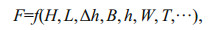 (5)
(5)where T is the wave period. The influence of panel length W can be negligible in this work since our concern is the uplift force per unit length perpendicular to the wave direction. Furthermore, the water depth h of this study is fixed at 0.4 m, and the wave length L can be determined by providing the wave period T through the dispersion relationship, we can skip either the wave length or the wave period. We chose the wave length L as a factor that influences the resultant wave uplift force in the following analysis. As a result, we simplify Eq.5 as follows:
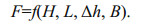 (6)
(6)In the following, the relationships between the wave uplift force F with respect to variables H, L, Δh, and B are analyzed in detail based on our laboratory results. The basic idea of our analysis is two-fold: (1) we change the variable of interest and examine the influence on the resultant wave uplift force, while (2) keeping other variables constant.
3.1 Impact of the wave height on the wave uplift forceBradner et al. (2011) suggested that the wave height has the largest effect on the measured forces. Therefore, the relationship between the uplift force and the wave height is first examined in this study. Figure 3 presents the relationship between wave height H and the wave uplift force F on the panel, where Fig. 3a shows the case with the panel width B=0.5 m and the clearance Δh=0.01 m. Similarly, Fig. 3b shows the case with the panel width B=1.0 m and the clearance Δh=0.01 m, and Fig. 3c shows the case with the panel width B=1.5 m and the clearance Δh=0.03 m. According to Fig. 3, we have two important observations: (1) when the panel width, the clearance, and the wave period are fixed, the wave uplift force on the panel is proportional to the wave height, and (2) when the panel width, the clearance, and the wave height are fixed, the longer the wave period, the larger the wave uplift force on the panels.

|
| Fig.3 The relationship of wave uplift force F on the panel with respect to the wave height H |
Figure 4 presents the relationship of wave uplift forces F with respect to the wave length L, where Fig. 4a shows the case with the panel width B=0.5 m. Similarly, Fig. 4b shows the case with the panel width B=1.0 m, and Fig. 4c shows the case with the panel width B=1.5 m. We also have two important observations: (1) when the panel width, the wave height, and the clearance are fixed, the wave uplift force on the panel is proportional to the wave length, and (2) when the panel width, the wave height, and the wave length are fixed, the smaller the clearance, the larger the wave uplift force on the panels. However, it should be pointed out that the phenomenon that the uplift force F increases with a longer wave length L is not applicable to all panel widths B. In fact, the relative panel width B/L plays a more important role in determining the wave uplift force, as to be shown below.

|
| Fig.4 The relationship of wave uplift force F on the panel with respect to the wave length L The wave height H≈0.123 m |
While Fig. 4 shows the variation of the uplift force F with respect to the wave length L, it also indicates that clearance Δh affects the wave uplift force. The relationship between the clearance and the uplift force is further analyzed in Fig. 5. For the clearance, we also consider different combinations of panel width, wave height, and wave period to obtain five curves. It is seen obviously that the wave uplift force decreases with the increase of the panel clearance. Although only three clearances are considered in this study, it could be expected that when the panel clearance continues to increase to a certain extent, the wave can not reach the panel, resulting in zero wave uplift force on the panel. Figure 5 further shows that the slope of the five curves are different, indicating that the panel width, the wave height, and the wave period (or wave length) influence the decreasing speed of the uplift force with the increase of the clearance.

|
| Fig.5 The relationship of wave uplift force F on the panel with respect to the clearance Δh Five curves are presented by choosing different panel width, wave height, and wave period. |
The impact of the panel width on the wave uplift force is shown in Fig. 6 with the clearance Δh=0.03 m. We can observe that the uplift force F tends to increase with the increase of the panel width B for the wave period larger than 1.0 s, while for T=1.0 s the uplift force tends to decrease with the increase of the panel width. This is because the wave uplift force is mainly determined by the ratio of panel width to wave length B/L, not just by panel width B or wave length L alone. For example, the wave length is 1.46 m for T=1.0 s, the panel width B=0.5 m, thus the relative panel width B/L=0.34, that is, the panel width is less than half the wave length. Under the wave action, the whole panel could be located in the wave crest as shown in Fig. 7. When the panel width B=1.0 m and 1.5 m, the width of the panel is more than half the wave length. As a result, some part of the panel is located in the wave crest area, while the other part is located in the wave trough area. Usually, the part located in the wave crest is subject to positive (upward) uplift forces and the part located in the wave trough is subject to negative (downward) forces. The downward force counteracts some of the uplift force so that the total uplift force decreases if B/L is larger than 0.5. For other cases with wave periods T=1.5 s, T=2.0 s, T=2.5 s, T=3.0 s, the corresponding wave lengths are 2.61, 3.69, 4.74, and 5.76 m, respectively. The panel widths B=0.5 m, B=1.0 m, and B=1.5 m are all less than (or slightly larger than) half of the wave length for those cases, consequently, the entire panel can be almost under the positive uplift force simultaneously. Therefore, with the increase of the panel width (or the contact area between the wave and the panel), the wave uplift force on the panel increases.

|
| Fig.6 The relationship of wave uplift force F on the panel with respect to the panel width B The clearance Δh=0.03 m. |

|
| Fig.7 Sketch map of the comparison between the three different panel widths B (0.5 m, 1.0 m and 1.5 m) and the wave length L=1.46 m |
We have shown in the previous section that wave uplift force on panels was affected by many factors, such as wave height, wave length, panel width, and the clearance. By using single-variable analysis, we demonstrated that appropriate relationships could be established between the wave uplift force and individual factors. These relationships can help us better understand the nature of the wave uplift force on horizontal panels.
In order to facilitate the application, a reliable and convenient empirical formula is needed. Although a few empirical formulas were reported in the literature, there are some shortcomings associated with them, as noted in the Introduction section. For instance, some formula involves complicated calculation. Furthermore, some formula does not consider the change of panel width along the wave direction. Moreover, the physical meanings of the formula or its variables are not clear at all. To address these limitations, the present study utilizes the dimensionless analysis technique and establishes an empirical formula based on our comprehensive laboratory measurements.
4.1 Dimensionless analysisThe dimensionless form of wave uplift force is in general preferred for engineering analysis. However, there is no consent of dimensionless forms yet. For example, Park et al. (2017) adopted F/(ρgH2W) for the wave uplift force and Δh/h for the clearance. While Cuomo et al. (2007) adopted Fzqs1/250/(ρgHsS) for the uplift force, and (ηmax–Δh)/h for the clearance. Tirindelli et al. (2004) adopted Fzqs/(ρgHsS) for the uplift force, and (ηmax–Δh)/Hs for the clearance. Isaacson and Bhat (1996) adopted B/L for the panel width B. The present study adopts the following parameters F/(ρgHS), (ηmax–Δh)/H, B/L and H/L. As a result, the wave uplift force F on the horizontal panel in the dimensionless form is expressed as:
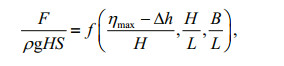 (7)
(7)where ηmax is the maximum wave surface elevation above the SWL.
4.1.1 Variation of the relative uplift force F/(ρgHS) with the relative clearance (ηmax–Δh)/HThe relationship between the relative uplift force F/(ρgHS) and the relative clearance (ηmax–Δh)/H is shown in Fig. 8. Figure 8a shows the variation of F/ (ρgHS) with respect to (ηmax–Δh)/H when the parameter B/L and H/L are fixed. It is seen that the magnitude of F/(ρgHS) approximately increases in a linear way with the increase of (ηmax–Δh)/H. Figure 8b shows the relationship between the relative uplift force F/(ρgHS) and the relative clearance (ηmax–Δh)/H when only B/L is fixed. It is seen that the relationship between F/(ρgHS) and (ηmax–Δh)/H is still approximately linear. In addition, we note that the slope of the linear relationship decreases with the increase of the relative panel width B/L. Based on the above observations, we assume that Equation 7 indicates a linear relationship between the wave uplift force F/(ρgHS) and the relative clearance (ηmax-Δh)/H, and the slope is influenced by the other two dimensionless variables: the relative panel width B/L and the wave steepness H/L.

|
| Fig.8 Relationship between the uplift force F/(ρgHS) and relative clearance (ηmax–Δh)/H There is an approximately linear relationship between the wave uplift fore and the relative clearance. |
The wave steepness maybe concerns the impact angle of wave train on horizontal panels. The relationship between the uplift force F/(ρgHS) and the wave steepness H/L obtained from this experiment study is shown in Fig. 9. The data points in Fig. 9 are divided into three categories according to the difference of the relative clearance (ηmax–Δh)/H, that is, (ηmax–Δh)/H≈0.21, (ηmax–Δh)/H≈0.35 and (ηmax-Δh)/H≈0.52. However, the relative panel width B/L is not fixed in each category. Figure 10 is similar.

|
| Fig.9 Relationship between the uplift force F/(ρgHS) and the wave steepness H/L Three power-law lines are fitted based on the scattered data points with the same clearance. |
It is seen that the uplift force F/(ρgHS) decreases with the increase of the wave steepness H/L, and finally tends to stabilize. The trend line between these two variables follows a power-law curve. We can see that their relationship is nonlinear, and the clearance (ηmax–Δh)/H is an important factor affecting the specific relationship between them. On the other hand, if we evaluate the same clearance (ηmax–Δh)/H data points, we could see that the larger the wave steepness, the smaller the wave uplift force. This observation means that the sign of variable c1 in Eq.8 is negative.
4.1.3 Variation of the relative uplift force F/(ρgHS) with the relative width B/LAs demonstrated in Section 3.4 and Fig. 6 that wave uplift force generally increases with the increase of panel width. However, that observation does not hold true when the wave is shorter (e.g T=1.0 s), we pointed out that the relative panel width B/L plays a critical role in determining the wave uplift force. The relationship between the relative wave uplift force F/ (ρgHS) and the relative panel width B/L is shown in Fig. 10.

|
| Fig.10 Relationship between the uplift force F/(ρgHS) and the relative width B/L Three power-law lines are fitted based on the scattered data points with the same clearance. |
It is seen that the fixed clearance (ηmax–Δh)/H, with the increase of the relative panel width B/L, the uplift force F/(ρgHS) tends to gradually decrease and finally tends to be stable, which is due to the downward wave force exerting on the panel. The trend line between these two variables also follows a power-law relationship. This observation indicates that the sign of variable b1 in Eq.8 is negative. When the relative panel width is small (B/L≤0.5), the entire horizontal panel is either at the wave crest or at the wave trough simultaneously. In other words, the entire horizontal panel is almost subject to the uplift force simultaneously, then the relative wave force F/(ρgHS) is greater. However, with the increase of the panel width (B/L > 0.5), one part of the panel is in the wave crest area and the other part is in the wave trough area. That is to say, some parts are subject to uplift forces, and the other parts are subject to downward forces, resulting in relatively smaller uplift forces. However, when the panel width increases to a certain extent (B/L≈1.0), the panel width is close to the wave length, and the distribution of uplift and downward forces are in the tendency of stabilization, and then the total uplift forces tend to be stable.
4.2 Empirical formulaBased on the above analysis, we have the following two important observations: (1) the relative uplift force F/(ρgHS) and (ηmax–Δh)/H are of approximately linear dependence, and the slope of the linear dependence is related to the relative panel width B/L and the wave steepness H/L; and (2) the relative uplift force F/(ρgHS) is nonlinearly related to the relative width B/L and the wave steepness H/L. It is approximately a power function according to the corresponding trend in Figs. 9 & 10. Therefore, the following empirical formula of wave uplift forces on the horizontal panel is established,
 (8)
(8)where a1, b1, c1 are coefficients to be decided through fitting by using the laboratory measurement. In this study, the ηmax is evaluated by the 2nd order Stokes wave theory (Zhou et al., 2004).
 (9)
(9)where sinh() and cosh() are the hyperbolic sine and cosine functions respectively.
According to the experiment data, Equation 8 is fitted to obtain the coefficients a1, b1 and c1 of 0.05, -0.12 and -0.45 respectively. The comparison between the calculated wave uplift force based on Eq.8 and the laboratory measurement is shown in Fig. 11. The xcoordinate shows the dimensionless experiment data Fexp/(ρgHS), and the y-coordinate shows the dimensionless calculated value Fcal/(ρgHS). The 45° dashed line indicates the ideal fitting. It can be seen that most of the data points are near the 45° dashed line, that is, the fitted value of Eq.8 agrees well with the experimental data, and the correlation coefficient R=0.92. It should be noted that the applicable scope of Eq.8 is 0 < (ηmax–Δh)/H < 0.9, 0.1 < B/L < 1.0, 0.015 < H/L < 0.09 and 0.07≤h/L≤0.27.

|
| Fig.11 Comparison between the experimental data and the calculated value based on Eq.8 The correlation coefficient R=0.92. |
Based on our comprehensive laboratory experiment, we conducted single-variable analysis and dimensionless analysis; and we proposed an empirical formula for estimating the wave uplift force on horizontal panels. This formula is simple in form and convenient for application. Although some empirical formulas have been reported in the literature as reviewed in the Introduction section, each empirical formula has its applicable scope. To evaluate the efficiency/accuracy of the present formula, we compare it with two existing formulas in this section by applying them to the laboratory data collected in this work.
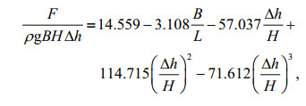
5.1 Comparison with Cuomo et al. (2007) formulaCuomo et al. (2007) proposed empirical formulas to calculate wave uplift force on panels at different locations of a horizontal panel, and the following two are most closely related to this study. One is an empirical formula for estimating the quasi-static uplift force on the internal deck element of a flat deck:
 (10)
(10)The other is an empirical formula for estimating the quasi-static uplift force on the external deck element of a flat deck:
 (11)
(11)The comparison among the calculated values by using Eqs.10 & 11 by Cuomo et al. (2007), the calculated value based on our empirical formula (i.e., Eq.8), and the laboratory measurement is shown in Fig. 12a & b, respectively. It is important to note that the Cuomo et al. (2007) formulas are for irregular waves, we replaced the significant wave height of irregular waves with the averaged wave height of regular waves in the calculation.

|
| Fig.12 Comparison between the calculated value of the formulas by Cuomo et al. (2007) Top panel: internal deck formula as Eq.10; bottom panel: external deck formula as Eq.11 and the calculation based on Eq.8. |
Figure 12 shows that the calculated values with Cuomo et al. (2007) formulas are roughly divided into three regions: B/L≤0.25, 0.25 < B/L≤0.5 and 0.5 < B/L. It is seen from Fig. 12a that the calculated value of Eq.10 by Cuomo et al. (2007) is generally greater than the laboratory measurements. In consideration of different relative panel width B/L, the agreement between the calculated value of the formula by Cuomo et al. (2007) and the laboratory measurements is relatively good when the relative panel width satisfies B/L≤0.25. With the relative panel width B/L > 0.25, the agreement between the calculated value of the Cuomo et al. (2007) formula and the experimental data is generally lower than the agreement at B/L≤0.25, and along with the increase of B/L, the deviation from the calculated value from the laboratory measurements tends to increase. Figure 12b considers the external deck formula of Cuomo et al. (2007) (Eq.11). Generally, the agreement between the calculated values with the experimental data in Fig. 12b is not as good as that in Fig. 12a. It is noted that the internal and external deck elements used by Cuomo et al. (2007) experiments were local smallscale decks, namely, B/L is relatively small. As a result, their formulas are more suitable for calculating the uplift force on the deck with a small relative width, as demonstrated in Fig. 12.
5.2 Comparison with Murali et al. (2009) formulaThe empirical formula proposed by Murali et al. (2009) to estimate wave uplift force on horizontal panels was Eq.4). It considers the influence of the relative panel width B/L and the clearance Δh/H on the uplift force. The comparison between the calculated value of the formula by Murali et al. (2009), the calculation based on our empirical formula as shown in Eq.8, and the experiment measurement is shown in Fig. 13. It is seen that calculation based on Murali et al. (2009) formula are much more scattered than that obtained by the present study. This phenomenon was caused by two reasons. One is that Murali et al. (2009) formula is only mathematical fitting of the experimental data, but its mechanism is not very clear; the other reason is that Murali et al. (2009) formula does not take into account the effect of wave steepness, which influences the attack angle of the wave on horizontal panels.

|
| Fig.13 Comparison between the calculated values based on Eq.8 with that of Murali et al. (2009) |
We have presented a comprehensive laboratory study of the uplift force on horizontal panels under the action of regular waves. We have established the relationship between the wave uplift force and different wave conditions and structure configurations, including the relative clearance, the relative width, and the wave steepness. Based on our laboratory findings, we have proposed a new empirical formula to calculate the wave uplift force on horizaontal panels. Finally, we verified the efficiency of our new formula by comparing with two existing formulas. The main conclusions of this study are summarized as follows:
(a) Single-variable analysis of the wave uplift force on horizontal panels
The laboratory measurements indicate that wave height H, wave length L (or wave period T), panel width B and clearance Δh are important factors affecting uplift forces on the horizontal panel. Specifically, the wave uplift force F increases with a larger wave height H, and the wave uplift force also increases with a longer the wave length L. However, the wave uplift force decreases with a larger clearance Δh. The impact of the panel width B on uplift forces is relatively complicated, and we found that the relative panel width B/L plays a critical role in determining the measured wave uplift force.
(b) The empirical formula to estimate the wave uplift force on the horizontal panels
Our dimensionless analysis showed that the uplift force F/(ρgHS) is proportional to the relative panel clearance (ηmax–Δh)/H, as shown in Fig. 8. However, the slope between those two variables is influenced by the wave steepness H/L and the relative panel width B/L. Specifically, (ⅰ) at a certain clearance (ηmax-Δh)/H, the uplift force F/(ρgHS) decreases with the increase of the wave steepness H/L, and finally tends to be stable, as shown in Fig. 9; (ⅱ) at a certain clearance (ηmax–Δh)/H, along with the increase of the relative panel width B/L, the uplift force F/(ρgHS) tends to gradually decrease, and finally tends to be stable, as shown in Fig. 10. Based on the above observations, we proposed the following empirical formula:

The applicable scopes of the present empirical formula is: 0 < (ηmax–Δh)/H < 0.9, 0.1 < B/L < 1.0, 0.015 < H/L < 0.09, and 0.07≤h/L≤0.27.
(c) The physical meaning and the efficiency of the empirical formula
In essence, the empirical formula proposed by this study is based on the physical process that the force is equal to the pressure times the area. Specifically, the force is the uplift force F, the pressure is the wave pressure ρgH, and the area is the panel area S. Unlike hydrostatic pressure, the wave impact pressure at the bottom of the panel is not uniform and varies in time. As a result, there should be a coefficient between the wave uplift force F and the product of the wave impact pressure ρgH and the panel area S, which shows the magnitude and distribution of wave impact pressure. Therefore, this coefficient should be related to the factors that affect the impact pressure at the bottom of the panel, such as the relative clearance, the wave steepness, and the relative panel width. Virtually the work of this paper was to explore this coefficient. Because of its aforementioned properties, the present empirical formula outperforms existing ones in calculating wave uplift force on horizontal panels. Overall, the empirical formula by this paper is simple in structure and has a definite physical mechanism. In the future, we will extend the present work to examine uplift force on horizontal panels induced by irregular waves.
7 DATA AVAILABILITY STATEMENTThe data that support the findings of this study are available from the corresponding author on request.
Bea R G, Xu T, Stear J, Ramos R. 1999. Wave forces on decks of offshore platforms. Journal of Waterway, Port, Coastal, and Ocean Engineering, 125(3): 136-144.
DOI:10.1061/(ASCE)0733-950X(1999)125:3(136) |
Bradner C, Schumacher T, Cox D, Higgins C. 2011. Experimental setup for a large-scale bridge superstructure model subjected to waves. Journal of Waterway, Port, Coastal, and Ocean Engineering, 137(1): 3-11.
DOI:10.1061/(ASCE)WW.1943-5460.0000059 |
Broughton P, Horn E, Anastasiou K, Shih R. 1988. Ekofisk Platform 2/4C:re-analysis due to subsidence. Proceedings of the Institution of Civil Engineers, 84(3): 619-622.
DOI:10.1680/iicep.1988.39 |
Cuomo G, Tirindelli M, Allsop W. 2007. Wave-in-deck loads on exposed jetties. Coastal Engineering, 54(9): 657-679.
DOI:10.1016/j.coastaleng.2007.01.010 |
French J A. 1969. Wave Uplift Pressures on Horizontal Platforms. California Institute of Technology, Pasadena, CA. 415p.
|
Hayatdavoodi M, Ertekin R C. 2016. Review of wave loads on coastal bridge decks. Applied Mechanics Reviews, 68(3): 030802.
DOI:10.1115/1.4033705 |
Hayatdavoodi M, Seiffert B, Ertekin R C. 2015. Experiments and calculations of cnoidal wave loads on a flat plate in shallow-water. Journal of Ocean Engineering and Marine Energy, 1(1): 77-99.
DOI:10.1007/s40722-014-0007-x |
Iemura H, Pradono M H, Takahashi Y. 2005. Report on the tsunami damage of bridges in Banda Aceh and some possible countermeasures. In: Proceedings of the 28th JSCE Earthquake Engineering Symposium. JSCE, Tokyo.p.214.
|
Isaacson M, Bhat S. 1996. Wave forces on a horizontal plate. International Journal of Offshore and Polar Engineering, 6(1): 19-26.
|
Jin J, Meng B. 2011. Computation of wave loads on the superstructures of coastal highway bridges. Ocean Engineering, 38(17-18): 2 185-2 200.
DOI:10.1016/j.oceaneng.2011.09.029 |
Murali K, Sundar V, Setti K. 2009. Wave-induced pressures and forces on deck slabs near the free surface. Journal of Waterway, Port, Coastal, and Ocean Engineering, 135(6): 269-277.
DOI:10.1061/(ASCE)0733-950X(2009)135:6(269) |
Park H, Tomiczek T, Cox D T, van de Lindt J W, Lomonaco P. 2017. Experimental modeling of horizontal and vertical wave forces on an elevated coastal structure. Coastal Engineering, 128: 58-74.
DOI:10.1016/j.coastaleng.2017.08.001 |
Seiffert B, Hayatdavoodi M, Ertekin R C. 2014. Experiments and computations of solitary-wave forces on a coastalbridge deck. Part Ⅰ:flat plate. Coastal Engineering, 88: 194-209.
DOI:10.1016/j.coastaleng.2014.01.005 |
Suchithra N, Koola P M. 1995. A study of wave impact of horizontal slabs. Ocean Engineering, 22(7): 687-697.
DOI:10.1016/0029-8018(95)00001-2 |
Tirindelli M, Cuomo G, Allsop W, McConnell K. 2004.Physical model studies of wave-induced loading on exposed jetties: towards new prediction formulae. In: Coastal Structures 2003. ASCE, Portland, Oregon, United States. p.382-393, https://doi.org/10.1061/40733(147)32.
|
Wang H. 1970. Water wave pressure on horizontal plate. Journal of the Hydraulics Division, 96(10): 1 997-2 017.
|
Wei Z P, Dalrymple R A. 2016. Numerical study on mitigating tsunami force on bridges by an SPH model. Journal of Ocean Engineering and Marine Energy, 2(3): 365-380.
DOI:10.1007/s40722-016-0054-6 |
Zhou Y R, Chen G P, Wang D T. 2004. Experimental study on total uplift forces on waves on horizontal plates. Journal of Hydrodynamics, 16(2): 220-226.
|