 2017, Vol. 35
Institute of Oceanology, Chinese Academy of Sciences
Article Information
- LIU Shuan(刘栓), ZHAO Xia(赵霞), ZHAO Haichao(赵海超), SUN Huyuan(孙虎元), CHEN Jianmin(陈建敏)
- Corrosion performance of zinc coated steel in seawater environment
- Chinese Journal of Oceanology and Limnology, 35(2): 423-430
- http://dx.doi.org/10.1007/s00343-016-5269-9
Article History
- Received Oct. 28, 2015
- accepted in principle Jan. 27, 2016
- accepted for publication Feb. 29, 2016


2 Key Laboratory of Marine Environmental Corrosion and Bio-Fouling, Institute of Oceanology, Chinese Academy of Sciences, Qingdao 266071, China
Zinc coated steel (ZCS) is one of the most common materials and has wide applications in automobiles, marine platforms, port docks, concrete structures, and the construction industry because of its relatively higher anti-corrosion performance and lower cost than those of mild steel (Chen et al., 2006; Nam et al., 2014). The protection obtained by zinc coating arises from its barrier and galvanic double protective effects (Koç et al., 2015). As a coating, it can provide a barrier effect that completely covers the steel surface and seals the steel from corrosive environments. Additionally, zinc is anodic to iron and behaves as a sacrificial material in humid and aqueous environments (Veleva et al., 2009; Hamlaoui et al., 2010; Posner et al., 2014).
Along with the continuous exploitation of marine resources, the increasing use of ZCS reinforcements in concrete structures and other marine constructions has driven research into the anticorrosion performance of ZCS subjected to seawater environments. Many laboratory studies and field exposure experiments on the atmospheric corrosion of ZCS have been carried out under different controlled conditions. Cachet et al.(2001, 2002) demonstrated that there are three parallel paths of zinc dissolution and three absorbed intermediates (Znad+, Znad2+, and ZnOHad) involved in the anodic oxidation process. Tsuru (2010) proposed that zinc ions dissolved from the corrosion products readsorb onto ZCS and prevent further corrosion of the steel substrate. In an unpolluted atmosphere, ZnO and Zn (OH)2 combined with Zn5(CO3)2(OH)6 were the most abundant corrosion products. On one hand, Deslouis et al. (1984) found that a passivation layer, mainly composed of ZnO, formed during the corrosion of zinc in an aerated, neutral 0.5 mol/L Na2SO4 solution. On the other hand, Boshkov (2003) reported that zinc coatings did not have a passivating effect in an aerated solution. However, few studies have been conducted to investigate the anticorrosion performance of ZCS in seawater environments, especially for long immersion. In our previous work, we demonstrated that corrosion products deposited on the surface of zinc coatings could induce pitting corrosion and were beneficial to the depolarization of cathodic reactions. High temperature could accelerate the corrosion rate of the zinc coating and inhibit the adsorption of corrosion products (Liu et al., 2012, 2013).
In this work, to obtain a better understanding of the corrosion performance of ZCS in seawater during long-term immersion, we investigated the corrosion behavior of ZCS at Qingdao test station for 180 days. Tafel polarization curves and linear polarization curves combined with EIS were measured to study the electrochemical corrosion behavior of the ZCS. Morphological and chemical characterization of the corrosion products were carried out using Fourier transform infrared spectroscopy (FTIR), X-ray diffraction (XRD), 3D digital microscopy, scanning electron microscopy (SEM), and energy dispersive spectroscopy (EDS). It is anticipated that the results will provide essential insight into the corrosion mechanism of ZCS in marine environments over long service times.
2 MATERIAL AND METHOD 2.1 Sample preparation and experimental set-up for electrochemical testsThe ZCS was purchased from BaoSteel, Shanghai, China. The chemical composition of the zinc coating was 0.04 wt% C, 0.2 wt% Mn, 0.01 wt% P, 0.008 wt% S, 0.036 wt% Ti, and the balance Zn. The thickness of the zinc coating was about 30 μm and its surface was smooth and compact. The ZCS samples were cleaned with acetone in an ultrasonic bath, rinsed with double distilled water, and then dried under a hot air stream. Corrosion experiments were conducted on electrodes with dimensions of 15 mm× 15 mm×3 mm and cold mounted in epoxy resin to give a working area of 1 cm2.
The seawater used for electrochemical tests was taken from Huiquan Bay, Qingdao, China. The experiment was carried out from December 2013 to May 2014. All tests were performed at room temperature (25±2℃), and the pH of the seawater was adjusted with dilute H2SO4 or NaOH solution.
The electrochemical corrosion tests were conducted using a classic three-electrode set-up. A platinum sheet (2.0 cm2) was used as the counter electrode, a saturated calomel electrode (SCE) was used as the reference electrode, and the ZCS working electrode (1×1 cm2) was placed parallel to the counter electrode. All the potentials give in this work are reported on the SCE scale. The ZCS working electrode was immersed in seawater for at least 30 min to attain a stable open circuit potential (OCP) before starting the electrochemical test. The polarization curves were recorded between -250 mV and +250 mV vs. OCP at a scan rate of 0.5 mV/s by changing the electrode potential automatically using a computer controlled EG & G 2273 potentiostat. For the linear polarization measurements, a sweep range of -10 mV to +10 mV vs. OCP at a sweep rate of 0.166 mV/s was used, and the polarization resistance (Rp) was determined from the slope of the potential (E) versus current (i) curve in the vicinity of the corrosion potential (Liu et al., 2013). The EIS measurements were carried out in the frequency range from 100 000 Hz to 0.01 Hz, and the amplitude of the AC signal was 10 mV. ZSimpWin 3.21 software and an appropriate equivalent circuit were used to analyze the obtained EIS data.
2.2 Observation and characterization of corrosion productsFourier transform infrared spectroscopy (FTIR) was used to analyze the corrosion products formed on the surface of the ZCS specimens. The background spectrum of the corrosion products were obtained from a pure KBr pellet with the same weight and size (Tomas et al., 2007). An X-ray diffractometer with Cu kα radiation (λ=0.154 nm) was used to obtain XRD patterns from powder scraped from the surface of the specimens. The scanning data were acquired in the angular range of 10°-80° (2θ) with a step size of 0.02° (2 θ) and a count time of 0.3 s/step. The data were evaluated using the MDI Jade 5.0 software package. The microstructure of the corrosion products was observed and recorded using a KH-7700 3D digital microscope and a JSM-6700F SEM instrument operated at a field emission energy of 10 keV. The chemical composition of the corrosion products was determined using a GENESIS 4000 energy dispersive spectroscope (EDS) attached to the SEM.
3 RESULT AND DISCUSSION 3.1 Polarization curves of ZCS after different immersion periods in seawaterImportant information on the kinetics of anodic and cathodic reactions can be directly obtained from polarization curves (Panagopoulos et al., 2013). Figure 1 depicts the Tafel polarization curves of ZCS specimens subjected to different immersion period (2, 60, 120, and 180 days) in seawater. Corrosion parameters including corrosion potential (Ecorr), corrosion current density (icorr), and the anodic and cathodic Tafel slopes (ba and bc), calculated from the curves using Powersuite software, are listed in Table 1.

|
| Figure 1 Tafel polarization curves of ZCS after different immersion periods in seawater a. 2 d; b. 60 d; c.120 d; d.180 d. |
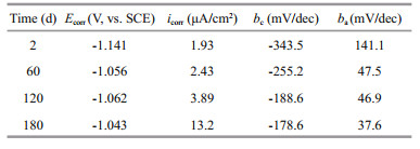
It is clear that the corrosion potential (Ecorr) shifted in the noble direction with increasing immersion time. This change in Ecorr was assumed to be related to the failure of the zinc coating. The corrosion current density (icorr) of the ZCS increased from 1.93 to 13.2 μA/cm with immersion time. The anodic Tafel slope ba decreased from 141.1 to 37.6 mV/dec, and the absolute value of the cathodic Tafel slope bc decreased from 343.5 to 178.6 mV/dec. These trends showed that the corrosion rate of the ZCS obviously increased with time in seawater during the long immersion period. It is well known that the corrosion rate of a metal is determined by the rates of both the anodic and cathodic reactions (Zou et al., 2011). In this study, the value of both ba and bc decreased remarkably with time, suggesting that the corrosion resistance of the ZCS gradually declined with increasing time in the seawater. Additionally, the value bc was much lower than that of ba for the whole immersion period, indicating that the corrosion rate of the ZCS was under cathodic control (Rosliza et al., 2010).
3.2 EIS curves of ZCS under different immersion times in seawaterEIS is an in situ, rapid, convenient, and nondestructive method that has many advantages over other traditional electrochemical techniques. The results of EIS measurements of the ZCS after different immersion periods in seawater are shown in Fig. 2. All obtained plots showed two apparent capacitive arcs. However, three time constants were observed from the Bode phase angle plots, because the second time constant was not clearly distinguishable owing to its overlap with the first time constant (Chen et al., 2004).

|
| Figure 2 Experimental Nyquist and Bode plots of ZCS after different immersion periods in seawater |
Based on the corrosion process of ZCS in seawater and the morphology of the corrosion products adsorbed on the specimen surface (Fig. 8), the equivalent circuit shown in Fig. 3 was produced to fit the EIS data. The fitted results are listed in Table 2.

|
| Figure 3 Equivalent circuit model used to fit the EIS data for ZCS in seawater |

In the equivalent circuit (Fig. 3), the capacitance was replaced by the constant phase angle element Q, because a dispersion effect can be caused by microscopic surface roughness (Liu et al., 2013; Sun et al., 2013; Zhao et al., 2014). Rs is the resistance of the solution. The high-frequency elements Q1 and Rout correspond to the capacitance and the corrosion products absorbed on the specimen; the medium-low frequency elements Q2 and Rpore are the capacitance and resistance of the pores (inner rust layer formed by localized corrosion); the low frequency elements Rct and C are the charge-transfer resistance and doublelayer capacitance, respectively. For the capacitive loops, the coefficients n1 and n2 represent the depressed feature in the Nyquist diagram.
The seawater resistance (Rs) was invariant during the whole immersion period. The change in the double-layer capacitance (C) was attributed to the varied change in the real area of the corroded specimen during the corrosion process, because the Zinc coating was subjected to different corrosion conditions and exposure time. During the 180-d immersion, the values of Rout and Rct decreased from 148.2 to 36.3 Ω cm2 and from 4 395 to 156.3 Ω cm2, respectively, indicating that the zinc coating was destroyed under the erosion effect of Cl- and its protective ability was subsequently reduced during the long-term immersion. However, Rpore increased from 14.36 to 189.3 Ω cm2 at the initial stage (120 d), and then decreased to 89.3 Ω cm2 after 180 days, suggesting that generation of an inner rust layer may have improved the corrosion resistance temporarily, although it was ultimately destroyed by Cl- erosion. Cl- is a strong anodic activator because of its small radius and volume, which allow it to penetrate through the initial corrosion product, destroy its structure (Rout), and react with the substrate metal directly, thereby generating an inner corrosion product (Rpore). Once Cl- had destroyed part of the zinc coating, the substrate metal was exposed and acted as an anode, while the corrosion products deposited on the surface of the zinc coating acted as a cathode. As a result, an activation-inactivation corrosion cell was formed, and the smaller anode vs. the larger cathode caused the corrosion of the ZCS to accelerate over the long immersion period in seawater (Sun et al., 2013).
3.3 effect of pH on corrosion behavior of ZCS in seawaterIn seawater, the main anodic and cathodic processes of ZCS corrosion are the dissolution of the zinc coating and the reduction of dissolved oxygen, respectively. In some closed environments, the pH of the seawater may increase during this corrosion process. Figure 4 shows the linear polarization curves of ZCS immersed in seawater of different pH, while Fig. 5 shows the variation in Rp and Ecorr observed as a function of pH. It is clear that Ecorr shifted from a negative value to a positive one with increasing pH; the linear polarization curve gradually became nonlinear. Thus, the fitted zone was restricted to the linear region (from -5 mV to +5 mV vs. SCE). A higher value of Rp suggests a lower ZCS corrosion rate (Rosliza et al., 2010; Wan Nik et al., 2011). The Rp of the ZCS increased gradually with pH, indicating that the corrosion resistance of the ZCS improved. This was probably caused by the generation of a passive film (mainly ZnO) on the zinc coating in the highly alkaline seawater. Large amounts of needle-like corrosion products became strongly and compactly adhered to the specimen surface at high pH, and little pitting corrosion of the ZCS occurred (Liu et al., 2012). These results were consistent with those of Yeomans (Yeomans et al., 2004). Therefore, it is possible that a stable passive film formed on the zinc coating and acted as protection against corrosion in highly alkaline conditions.

|
| Figure 4 Linear polarization curves of ZCS immersed in seawater of different pH |

|
| Figure 5 Evolution of Rp and Ecorr of ZCS estimated from linear polarization curves (Fig.4) at different seawater pH |
To further investigate the corrosion behavior of ZCS, the corrosion products deposited on the surface of ZCS during immersion in seawater were analyzed by XRD, FTIR, 3D digital microscopy, SEM, and EDS.
The XRD spectrum of ZCS (Fig. 6) immersed in seawater for 180 d showed prevailing contributions from Zn5(OH)8Cl2 and Zn (ClO4)2, with small contributions from Zn (OH)2 and ZnO, with some very low intensity peaks which require further analysis for assignment. Solid corrosion products scraped from the surface of the zinc coating were analyzed by FTIR (Fig. 7). different compounds have characteristic absorptions at different positions (Qu et al., 2005). ZnO only has bands in the 350-600/cm region, which correspond to the Zn-O bond. Zn5(OH)8Cl2 has strong bands at 3 450/cm and weak bands at 730, 900, and 1 620/cm. Zn5(OH)6(CO3)2 has strong bands at 1 380 and 1 510/cm, which correspond to the asymmetric stretching vibrations of the carbonate ion, and also has bands at 1 040, 830, and 735/cm (Qu et al., 2002). Therefore, the peak at 478/cm in the obtained spectrum was the Zn-O bending vibration band, the peaks at 837, 1 033, 1 382, and 1 531/cm indicated the presence of Zn5(OH)6(CO3)2, and the peaks at 941, 2 379, and 3 400/cm were attributed to Zn5(OH)8Cl2. The combined XRD and FTIR results indicated that the main corrosion products on the ZCS were Zn5(OH)8Cl2, Zn5(OH)6(CO3)2, and ZnO.

|
| Figure 6 XRD spectrum of ZCS immersed in seawater for 180 days |

|
| Figure 7 FTIR of the corrosion product of ZCS immersed in seawater for 180 days |
Figure 8 shows the typical morphology of the corrosion products on the ZCS samples after different immersion periods in seawater. The observed corrosion products differed greatly in size. The small needle-like particles displayed a strong tendency to accumulate in the form of large aggregates (Fig. 8c). These porous corrosion products were beneficial to the absorption of dissolved oxygen, and likely accelerated the oxygen reduction reaction (Liu et al., 2012). The zinc coating was gradually damaged and non-uniform corrosion occurred on the ZCS after the corrosion products were removed from the specimen (Fig. 8d). For better analysis of the corrosion depth and microstructure of the ZCS after different immersion periods, Fig. 9 shows 3D digital micrographs of ZCS specimens immersed in seawater for 90 and 180 d. The color of the corrosion product grew dark, and the areas of pitting corrosion became larger with increasing immersion time. The surface of the zinc coating was damaged obviously by the pitting corrosion, and the average corrosion depth was found to be 750 μm after 180 d immersion.

|
| Figure 8 SEM images of ZCS immersed in seawater for different periods a. 30 d; b. 60 d; c. 180 d; d. 180 d (after corrosion products were scraped from the zinc coating). |

|
| Figure 9 3D digital micrographs of ZCS immersed in seawater for (a) 90 d and (b) 180 d |
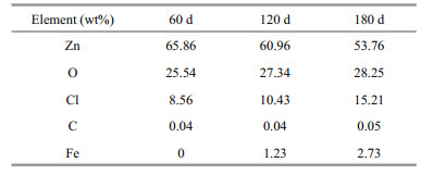
EDS analysis (Table 3) revealed that the main component elements of the corrosion products were Zn, Cl, Fe, O and very small amounts of C. Both the O content and Cl content of the corrosion products increased with the immersion time in seawater. Fe element was detected after 120 d, and its content then gradually increased with time. This indicated that the zinc coating had become damaged and the substrate Fe had been exposed to the seawater and acted as an anode. The presence of Cl element implied that Cl- not only played a role as a catalyst but also as a reactant.
|
The corrosion performance of ZCS in seawater during long-term immersion was investigated. Polarization curves, linear polarization curves, and EIS as well as a number of characterization methods were used to study the corrosion mechanism of the ZCS in detail. The primary conclusions were as follows:
(1) the rate of ZCS corrosion increased with time in seawater during long-term immersion;
(2) the zinc coating was damaged and non-uniform corrosion occurred under Cl- erosion;
(3) the average pitting corrosion depth was 750 μm after 180 days;
(4) the corrosion rate of the ZCS decreased as the pH of the seawater was increased. A stable passive film generated and formed a protective layer on the ZCS under highly alkaline conditions;
(5) the main corrosion products generated on the ZCS were Zn5(OH)8Cl2, Zn5(OH)6(CO3)2, and ZnO. Porous corrosion products were beneficial to the cathodic depolarization reaction.
5 ACKNOWLEDGMENTWe would like to thank Dr. ZHAO Xiaorong of China Three Gorge University for her assistance in revising the draft manuscript.
| Boshkov N, 2003. Galvanic Zn-Mn alloys-electrodeposition, phase composition, corrosion behaviour and protective ability. Surface and Coatings Technology, 172(2-3): 217–226. Doi: 10.1016/S0257-8972(03)00463-8 |
| Cachet C, Ganne F, Joiret S, Maurin G, Petitjean J, Vivier V, Wiart R, 2002. EIS investigation of zinc dissolution in aerated sulphate medium. Part Ⅱ:zinc coatings.Electrochimica Acta, 47(21): 3409–3422. |
| Cachet C, Ganne F, Maurin G, Petitjean J, Vivier V, Wiart R, 2001. EIS investigation of zinc dissolution in aerated sulfate medium. Part I:bulk zinc. Electrochimica Acta, 47(3): 509–518. |
| Chen Y L, Zhang Z, Cao F H, Li J F, Zhang J Q, Wang J M, Cao C N, 2004. A study of the corrosion of aluminum alloy 2024-T3 under thin electrolyte layers. Corrosion Science, 46(7): 1649–1667. Doi: 10.1016/j.corsci.2003.10.005 |
| Chen Y Y, Chung S C, Shih H C, 2006. Studies on the initial stages of zinc atmospheric corrosion in the presence of chloride. Corr osion Science, 48(11): 3547–3564. Doi: 10.1016/j.corsci.2005.12.007 |
| Deslouis C, Duprat M, Tulet-Tournillon C, 1984. The cathodic mass transport process during zinc corrosion in neutral aerated sodium sulphate solutions. Journal of Electroanalytical Chemistry and Interfacial Electrochemistry, 181(1-2): 119–136. Doi: 10.1016/0368-1874(84)83624-2 |
| Hamlaoui Y, Tifouti L, Pedraza F, 2010. On the corrosion resistance of porous electroplated zinc coatings in different corrosive media. Corr osion Science, 52(6): 1883–1888. Doi: 10.1016/j.corsci.2010.02.024 |
| Koç E, Kannan M B, Ünal M, Candan E, 2015. Influence of zinc on the microstructure, mechanical properties and in vitro corrosion behavior of magnesium-zinc binary alloys. Journal of Alloys and Compounds, 648: 291–296. Doi: 10.1016/j.jallcom.2015.06.227 |
| Liu S, Gu Y, Wang S L, Zhang Y, Fang Y F, Johnson D M, Huang Y P, 2013. Degradation of organic pollutants by a Co3O4-graphite composite electrode in an electro-Fentonlike system. Chinese Science Bulletin, 58(19): 2340–2346. Doi: 10.1007/s11434-013-5784-4 |
| Liu S, Sun H Y, Sun L J, Fan H J, 2012. Effects of pH and Clconcentration on corrosion behavior of the galvanized steel in simulated rust layer solution. Corr osion Science, 65: 520–527. Doi: 10.1016/j.corsci.2012.08.056 |
| Liu S, Sun H Y, Zhang N, Sun L J. 2013. The corrosion performance of galvanized steel in closed rusty seawater.International Journal of Corr osion, 2013: 267353. |
| Nam N D, Mathesh M, Van Le T, Nguyen H T, 2014. Corrosion behavior of Mg-5Al-xZn alloys in 35 wt.% NaCl solution. Journal of Alloys and Compounds, 616: 662–668. Doi: 10.1016/j.jallcom.2014.07.014 |
| Panagopoulos C N, Georgiou E P, Markopoulos C, 2013. Corrosion and wear of zinc in various aqueous based environments, Corr osion Science, 70:62-67. Corr osion Science, 70: 62–67. Doi: 10.1016/j.corsci.2013.01.012 |
| Posner R, Fink N, Giza G, Grundmeier G, 2014. Corrosive delamination and ion transport along stretch-formed thin conversion films on galvanized steel. Surface and Coatings Technology, 253: 227–233. Doi: 10.1016/j.surfcoat.2014.05.041 |
| Prosek T, Thierry D, Taxén C, Maixner J, 2007. Effect of cations on corrosion of zinc and carbon steel covered with chloride deposits under atmospheric conditions. Corr osion Science, 49(6): 2676–2693. Doi: 10.1016/j.corsci.2006.11.004 |
| Qu Q, Li L, Bai W, Yan C W, Cao C N. 2005. Effects of NaCl and NH4Cl on the initial atmospheric corrosion of zinc. Corr osion Science, 47(11):2 832-2 840. |
| Qu Q, Yan C W, Wan Y, Cao C N, 2002. Effects of NaCl and SO2on the initial atmospheric corrosion of zinc. Corr osion Science, 44(12): 2789–2803. Doi: 10.1016/S0010-938X(02)00076-8 |
| Rosliza R, Wan Nik W B, Izman S, Prawoto Y, 2010. Anticorrosive properties of natural honey on Al-Mg-Si alloy in seawater. Current Applied Physics, 10(3): 923–929. Doi: 10.1016/j.cap.2009.11.074 |
| Rosliza R, Wan Nik W B, 2010. Improvement of corrosion resistance of AA6061 alloy by tapioca starch in seawater. Current Applied Physics, 10(1): 221–229. Doi: 10.1016/j.cap.2009.05.027 |
| Sun H Y, Liu S, Sun L J, 2013. A Comparative study on the corrosion of galvanized steel under simulated rust layer solution with and without 3. 5wt%NaCl. International Journal of Electrochemical Science, 8(3): 3494–3509. |
| Tsuru T, 2010. Various electrochemical approaches for corrosion engineering. Zairyo-to-Kankyo, 59(11): 404–409. Doi: 10.3323/jcorr.59.404 |
| Veleva L, Acosta M, Meraz E, 2009. Atmospheric corrosion of zinc induced by runoff. Corr osion Science, 51(9): 2055–2062. Doi: 10.1016/j.corsci.2009.05.030 |
| Wan Nik W B, Zulkifli M F, Rosliza R, Ghazali M J, Khaled K F, 2011. Potential of honey as corrosion inhibitor for aluminium alloy in seawater. World Applied Sciences Journal, 14(2): 215–220. |
| Yeomans S R. 2004. Galvanized Steel Reinforcement in Concrete. Elsevier, Oxford. p.113-117. |
| Zhao X, Liu S, Wang X T, Hou B R, 2014. Surface modification of ZrO2 nanoparticles with styrene coupling agent and its effect on the corrosion behaviour of epoxy coating. Chinese Journal of Oceanology and Limnology, 32(5): 1163–1171. Doi: 10.1007/s00343-014-3327-8 |
| Zou Y, Wang J, Zheng Y Y, 2011. Electrochemical techniques for determining corrosion rate of rusted steel in seawater. Corr osion Science, 53(1): 208–216. Doi: 10.1016/j.corsci.2010.09.011 |