 2017, Vol. 35
Institute of Oceanology, Chinese Academy of Sciences
Article Information
- ZHAO Xia(赵霞), CHEN Changwei(陈长伟), XU Weichen(徐玮辰), ZHU Qingjun(朱庆军), GE Chengyue(戈成岳), HOU Baorong(侯保荣)
- Evaluation of long-term corrosion durability and self-healing ability of scratched coating systems on carbon steel in a marine environment
- Chinese Journal of Oceanology and Limnology, 35(5): 1094-1107
- http://dx.doi.org/10.1007/s00343-017-6132-3
Article History
- Received Apr. 30, 2016
- accepted in principle Jun. 6, 2016
- accepted for publication Jul. 5, 2016


2 School of Civil Engineering, Qingdao Technological University, Qingdao 266033, China
Organic coatings are one of the most wide spread methods for anticorrosion of different engineering structures in marine environments. Polymer coatings can improve the corrosion resistance and durability of metal structures (Twite and Bierwagen, 1998; Chen et al., 2013). In general, protection against corrosion can be accomplished by passive protection, which results in the high adhesion of a coating to a protected surface and the creation of a barrier against corrosive species (Almeida et al., 2005; Blustein et al., 2007; Raps et al., 2009; Saremi and Yeganeh, 2014), or by active protection through the modification of a coating with anticorrosion additives.
The formation of coating defects is inevitable during their preparation or application (Zin et al., 2005; Ecco et al., 2014). Organic solvent evaporation may leave some pores during curing, which can weaken the protective effect of the coating. External mechanical shock can lead to obvious defects in the organic-coatings surface, which reduces the protection and allows the corrosive species to arrive directly at the naked metal surface. If metals were covered with a damaged coating and were exposed for an extended period, the metal corrosion rate would increase rapidly because of an aggressive amount of corrosive ions (Schneider and Kelly, 2007). Exposure of the coatings to aqueous electrolyte solutions may also cause swelling of some parts of the coatings and yield numerous new conductive pathways. The polymer coating itself cannot protect the defective zone and is unable to inhibit the propagation of defects once corrosion occurs (Zheludkevich et al., 2010). Therefore, an improvement in the durability of damaged coatings has become a recent issue of interest.
Shao et al. (2009) studied the role of a zinc phosphate pigment in the corrosion of scratched epoxy-coated steel via electrochemical impedance spectroscopy (EIS), electrochemical noise measurement and scanning electrochemical microscopy. The zinc phosphate exhibited an inhibition effect in the corrosion of the scratched epoxy-coated steel, and the scratched surface under the zinc-phosphate coating could be re-healed by an insulating film. Pilbáth et al. (2012) carried out scratch tests on epoxy-coated steel samples with and without microcapsulated linseed oil, and, in acidic solution, studied the release of the oil from the capsules at the damaged sites and its protection efficiency. Near the local damage, the cathodic-reduction and anodicoxidation reactions indicated that the coating with microcapsules could decrease the corrosion rate of the coating spontaneously, which proved the concept of coating self-repair. Yeganeh and Keyvani (2016) produced functionalized mesoporous silica that was loaded by a molybdate-ion corrosion inhibitor and dispersed it in epoxy coatings. The composited coating had the highest anticorrosion ability compared with the pure epoxy resin and the epoxy resin that contained mesoporous silica when immersed in NaCl solution for 56 d. The scratch zone could be healed by constant molybdate release in response to the change in zeta potential of the mesoporous silica. Balusamy and Nishimura (2016) studied the corrosion behavior of scratched epoxy-coated carbon steel in a simulated pore solution that contained various concentrations of chloride ions (as NaCl) by localized EIS. It was concluded that 0.05% NaCl can be considered as a threshold level of the chloride ion concentration in the simulated pore solution. A continuous decrease in |Z| at the scratch results from the higher extent of Fe dissolution. Zhang et al. (2014) demonstrated the use of corrosion inhibitor-embedded spherical micro-pits that were fabricated with cetyltrimethyl ammonium bromide as the etching template for self-healing corrosion protection. Yabuki et al. (2014) reported self-healing polymer coatings with cellulose nanofibers that served as pathways to release a corrosion inhibitor. The results at 24 h showed that the synergistic polarization resistance of the scratched samples that contained nanofibers and a corrosion inhibitor was higher than that of the organic coating that contained only corrosion inhibitor. The effect of the two materials can result in a better performance of the damaged coating. Thiourea is an excellent corrosion inhibitor that is affordable, used widely and easily obtained (Karthik et al., 2014; Fouda and Soliman, 2015). Lin et al. (1999) reported thiourea as a corrosion inhibitorin steel in 3.5% NaCl solution and in seawater. Trace amounts of thiourea can enhance steel protection by nearly 50%. In addition, fibers can distribute in the coating like a network and provide physical barriers to the corrosive media, acting as a channel to release corrosion inhibitors (Yabuki et al., 2014). The synergistic effect of these two materials for corrosion protection of carbon steel was discussed in this paper.
EIS measurements are used extensively to investigate the degradation of polymer-coated metals (Bonnel et al., 1999; Campos et al., 2007; Gonçalves et al., 2011; Gergely et al., 2012). However, EIS can only provide average signals of the entire interface and can not reveal local information regarding the damaged part (Zhao et al., 2007), so other techniques are required for further study of the scratched coating. A wire beam electrode (WBE) is a regular array that is formed by many mini-electrodes (namely wires), and all electrodes are separated from one another by a thin insulating film. The WBE was originally developed to study the electrochemical heterogeneity of organic coatings by scanning the electrode surface to obtain the current and potential distribution (Tan, 1991; Tan et al., 2006a, b) demonstrated the applicability of WBE to investigate the origin of spontaneous electrode potential/current fluctuations and the effects on electrochemical processes. Thu Le et al. (2005) obtained non-uniformity and a delamination rate near the artificial coating defect by using a modified WBE.
In general, protective coating systems have been used for a long time in practical engineering, therefore, a long-term evaluation of the damaged coating with functional additives should be more convincing, and the evaluation results would be more instructive. However, there is a lack in the literature of evaluating data on the protective coating on a metal surface for more than 100 d. In this work, the role of glass fibers and thiourea in a polymer-coating system immersing in 3.5% NaCl for 120 d was studied, and the longterm protective and self-healing properties of coating systems were evaluated by EIS, WBE and other techniques. The results are expected to provide an important reference for the future development of novel polymer-coating system and allow for a prediction of the life span of coatings with defects.
2 MATERIAL AND METHOD 2.1 Material 2.1.1 ElectrodesTwo types of electrodes were used. The first was of Q235 steel samples that were cut to 10 mm×10 mm×10 mm. The Q235 steel has a classical composition (wt.%) of 0.14–0.22 C, 0.30–0.65 Mn, ≤0.30 Si, ≤0.045 P, ≤0.055 S and the remainder Fe. The experimental test block surfaces, with the exception of the working surface (10 mm×10 mm), were encapsulated by epoxy and polyamide resin of a certain proportion. Before testing, the surfaces of every specimens were treated gradually using SiC abrasive paper to 800 grit, and were then degreased ultrasonically with acetone, rinsed with distilled water and dried in air.
The second type of electrode was a WBE, as shown in Fig. 1a, in which 121 microelectrodes were fabricated from Q235 carbon steel wire (1 mm diameter). The microelectrodes were arranged regularly in an 11×11 matrix and were embedded in an epoxy resin at 0.6 mm intervals. Each microelectrode acted as a galvanic current sensor and substrate. The total area occupied by the 121 microelectrodes was approximately 0.95 cm2. The WBE surface was ground sequentially using a series of mesh silicon-carbide emery papers (#400, #600, #800 and #1000), degreased with acetone and then rinsed with deionized water. The WBE was placed horizontally in the chamber and the surfaces were covered with three paint-based layers.

|
| Figure 1 Electrodes used in the experiments a. WBE specimen; b. scratched electrode. |
Three paint-based layers that consisted of primary, middle and top coats were applied to a pretreated substrate. A zinc-rich inorganic coating with a solid content of 72% was applied to the steel as a primary coat, in which the zinc-particle diameter was ~2–5 μm. Before varnishing, the viscosity was adjusted using alcohol for ~18–20 s. An epoxy resin that contains micaceous iron oxide with a solid content of 75% was used as the middle coat. Before varnishing, the viscosity was controlled using a mixed solvent of dimethylbenzene and n-butyl alcohol for ~25–28 s. A polyurethane top coat witha solids content of 56% anda viscosity of ~18–20 s was used. The viscosity was tested using a Ford cup 4 according to GB/T 1723-1993. Paints were provided by the Marine Chemical Research Institute, Qingdao, China.
Different concentrations of glass fibers (diameter: ~2–6 μm, length: ~50–60 μm, Research Institute of Beijing National Institute of Technology) and thiourea (Sinopharm Chemical Reagent Co. Ltd., China) as a corrosion inhibitor were mixed into the middle coat using an ultrasonic homogenizer. The proportion of fibers in the middle coat after viscosity adjustment was between 0.3 wt.% and 1 wt.%, and for thiourea, it was between 0 wt.% and 0.7 wt.%.
Three coating layers were painted simultaneously on the working electrode surface by hand. The amount of each layer was controlled by the weight-loss method. The procedure was to apply primer first, then to apply a middle coat with or without glass fibers and thiourea, and finally, to apply a topcoat. Each layer of paint was dried at room temperature for 24 h before the next layer was applied. The thicknesses of the cured primer, middle and top coats were measured using a PosiTector6000FNS1 apparatus (Defelsko Company, New York, America), and they were ~15±2 μm, 20±2 μm and 15±2 μm, respectively.
Before conducting the experiments, the coated samples were cured at (25±2)℃ and (55%±5%) RH for 7 d. A round scratch (1mm diameter) was made using a steel needle (rotated through 360°) in the middle of the cured coating surface. The WBE defect with a 1-mm diameter is shown in Fig. 1b. Each electrochemical test was performed in 350 mL 3.5 wt.% NaCl solution, and the self-healing properties of the specimens were evaluated based on the corrosion behavior observed at the scratched portion of each specimen.
2.2 Method 2.2.1 EISEIS was used to evaluate the electrochemical behavior of the coated panels in 3.5 wt.% NaCl solution at room temperature for up to 120 d. EIS data were measured by using a Solartron 1287/1260 electrochemical analyzer (AMETEK, Inc., England). A classical three-electrode cell system was used. A saturated calomel electrode was used as the reference electrode, a platinum plate wire served as the counter electrode and a coated metallic substrate served as the working electrode. EIS measurements were conducted from 100 kHz to 10 mHz. A sinusoidal alternating current perturbation of 20 mV (rms) amplitude with respect to the open-circuit potential (OCP) was applied, and the EIS data collected were analyzed and fitted to several electrical equivalent circuit models using ZSimpWin software.
2.2.2 Polarization measurementsPolarization measurements were performed on panels immersed for 120 d in 3.5 wt.% NaCl solution using a Solartron 1287/1260 electrochemical analyzer (AMETEK, Inc., Leicester, England). The cathodic and anodic polarization curves were measured at a sweep rate of 1 mV/s, the scan range was ±1 V with respect to the OCP, and the carbon-steel surface area was 1 cm2.
2.2.3 Current determinationThe galvanic currents of individual wire electrodes in the WBE and all other wires shorted together were connected and recorded. An automatic measurement system based on modular instrument software (Chen et al., 2014) was used to measure the current fluctuation of each wire against the remaining wires of the entire wire beam. All measurements were controlled by a computer with in-house software in a LabVIEW environment. During current measurements, the interval between two channels was 1 s. Current distribution maps were drawn using Surfer 8.0 software.
2.2.4 CharacterizationThe morphology of the coated panels was studied by Hitachi S-3400 field emission scanning electron microscope (SEM, Hitachi Limited, Tokyo, Japan) at 25 kV. The presence of elements was determined by Hitachi S-3400 field emission energy dispersive spectrometry (EDS, Hitachi Limited, Tokyo, Japan). X-ray diffractometry (XRD) was conducted on a D8 Advance diffractometer (Bruker Company, Karlsruhe City, Germany) with CuKα radiation (λ=0.154 18 nm). The current was adjusted to 50 mA. The voltage was increased to 40 kV. The reflection angle 2θ ranged between 10° and 80°.
3 RESULT AND DISCUSSION 3.1 EIS measurementsTo determine the optimal fiber content, the protective performance of an epoxy coating with a fiber concentration from 0 wt.% to 1 wt.% was evaluated. Different concentrations of thiourea were added to the middle coat with optimal fiber content.
3.1.1 EIS of scratched-coating systems with fibersEIS plots of five coating systems that contain different fiber concentrations (i.e., 0 wt.%, 0.3 wt.%, 0.5 wt.%, 0.8 wt.% and 1 wt.%) in 3.5 wt.% NaCl solution as a function of time are presented in Fig. 2.

|
| Figure 2 EIS plots of coating systems with different fiber contents after immersion for 7 d in 3.5 wt.% NaCl solution a. Nyquist plot; b. Bode plot. |
When the fiber content was 0.5%, the radius of the capacitive arc in the Nyquist plot was significantly larger. |Z| was approximately five times higher than that of the other coating systems, which indicates the good barrier performance of the coating system with 0.5% fiber content for corrosive particles. This occurs because a small amount of fiber could not fill the natural pores and corrosive ions could still penetrate the coating and enter the coating/metal interface, whereas, for a large amount of fiber, fiber agglomeration may cause coating heterogeneity and result in many acquired pores existing in the coating. Therefore, 0.5 wt.% was selected as the optimum fiber content in the following study.
3.1.2 EIS of scratched-coating systems with fibers and thiourea 3.1.2.1 EIS plotsThe anti-corrosion performance of the coating with 0.5 wt.% fiber and different contents of thiourea at different immersion times in 3.5 wt.% NaCl solution was characterized by EIS, as shown in Fig. 3.

|
| Figure 3 EIS plots of coating systems with 0.5 wt.% fibers and different thiourea contents at different immersion times in 3. wt.% NaCl a and b. 0 wt.%; c and d. 0.3 wt.%; e and f. 0.5 wt.%; g and h. 0.7 wt.%. a. c. e and g are Nyquistplots, b. d. f and h are Bode plots. |
For a coating system with fibers only, as shown in Fig. 3a and b, the radius of the capacitive arc in the Nyquist plot and the |Z| value in the Bode plot increased during the initial immersion period and then decreased gradually with time. A peak appeared on the tenth day, and the maximum |Z| was ~3.2×10⁵ Ω cm2. When 0.3 wt.% thiourea was added into the coating system with fibers (Fig. 3c and d), the changing trend in Nyquist and Bode plots was similar to that without thiourea as shown in Fig. 3a. A peak value appeared on the tenth day and the maximum |Z| was also ~3.2×10⁵ Ω cm2. After 120 d, |Z| of the coating system with 0.3 wt.% thiourea was 4.4×10⁴ Ω cm2, which was slightly higher than that of the coating system without thiourea at 3.9×10⁴ Ω cm2.
Because 0.7 wt.% thiourea was mixed into the coating system, all of the maximum |Z| values in the Bode plot were lower than 105 Ω cm2. With an increase in time, corrosion spread and corrosion products sealed the scratched part. From the thirtieth day of immersion onwards (Fig. 3g and h), a capacitive arc and diffusion tail in the low-frequency range, as related to Warburg impedance, were visible. The linear tail could be attributed to oxygen diffusion through the corrosion product layers (Jorcin et al., 2006), which implies that a large number of corrosion products accumulated on the defects. The corrosion rate of the base metal increased, and a diffusion layer formed at the electrode/coating interface (Doherty and Sykes, 2004).
Because the thiourea content was 0.5 wt.% (Fig. 3e and f), the coating showed relatively good long-term self-healing behavior. At the beginning of immersion, the radius of the capacitive arc in the Nyquist plot and |Z| in the Bode plot increased gradually with time. The |Z| value reached 2.6×10⁵ Ω cm2 on the twentieth day. Thereafter, the radius of the capacitive arc and |Z| in the Bode plot decreased gradually. From the fiftieth day onwards, the radius of the capacitive arc and |Z| in the Bode plot increased simultaneously again, which indicates the enhanced corrosion resistance of the coating. Increases in total impedance indicated that the increasing corrosion resistance of the coating is attributed to the formation of a protective layer on the metal surface (Conde and Damborenea, 2002). Up to a 70-d immersion time, the maximum |Z| was 4.0×10⁵ Ω cm2, which is seven times higher than that at the initial time. A relatively high-level steady state was achieved from the ninetieth day onwards. In general, the coating with 0.5 wt.% fibers and 0.5 wt.% thiourea showed good corrosion protection performance and long-term effects for self-healing of carbon-steel surfaces, comparing with other coating systems. A certain amount of thiourea can delay electrolyte and Cl– penetration through the coating, thereby enhancing its barrier property.
3.1.2.2 Fitted parametersTo analyze the corrosion behavior of the coatings, three equivalent circuits as shown in Fig. 4 were used to fit the EIS spectra at different immersion times. To ensure heterogeneity of the protective coating, a constant phase-angle element Q was used in the equivalent circuit to represent the capacitance. The impedance of Q is defined as: ZQ=1/Y0(jω)n, where Y0 is the modulus, j is the imaginary number, ω is the angular frequency, and n is the phase (Wang et al., 2014; Zhang et al., 2016). Rs represents the solution resistance and R c and Qc are the coating resistance and coating capacitance, respectively. Rct and Qdl represent the charge-transfer resistance and double-layer capacitance (Zhao et al., 2014). At an initial immersion time, there was good adhesion between the coating and the substrate. Everything except the scratched part of the coating was intact, water has not yet reached the interface of the coating/metal, and the intact part can still play a protective role for the substrate. Therefore, it was reasonable to analyze the EIS plots with a series-parallel equivalent circuit regarding the coating film as a capacitor, as shown in Fig. 4a (Zhang et al., 2004). To distinguish the effect of water transportation over time, Model b as shown in Fig. 4b was used to simulate the state of the coating that was starting to delaminate from the substrate without corrosion products accumulating on the metal surface. Under this circumstance, protection of the coating decreased with time, but no diffusion characteristics were visible in the EIS plots. With continuous corrosion, corrosion products accumulated on the metal surface and prevented ion diffusion. Warburg impedance (Zw) was introduced to show that the electrode process was affected by the corrosion products (Cheng et al., 2004), so model c in Fig. 4 was used. Among the above parameters, Rc was the most intuitive parameter to reflect the protective ability of the coating system, and the dependence of Rc on time can help identify features of the deterioration process more clearly.

|
| Figure 4 Equivalent circuits of metal/epoxy coating systems under different immersion times in 3.5 wt.% NaCl solution a. at the initial time; b. in the medium term; c. at the later stage. |
To facilitate subsequent analysis, three scratched coating systems were used: Coating A contained no fibers and thiourea, Coating B contained 0.5 wt.%fi bers and Coating C contained 0.5 wt.% fibers and 0.5 wt.% thiourea. The dependence of Rc of the three coating systems on immersion time is shown in Fig. 5. The deterioration and self-healing processes of different coating systems were analyzed by Rc. The Rc of scratched Coating A decreased from an initial value of 1.5×10⁵ Ω cm2 to 8×10³ Ω cm2 after immersion for 15 d and was then maintained at a low level afterwards. Coating A system showed no self-healing properties for the scratched part during the entire immersion time. The R c of scratched Coating B increased at the initial time, reached a maximum on the tenth day (4.4×10⁵ Ω cm2), and showed a downward trend with time. These results indicate that fibers could be separated out from Coating B with water swelling, and then covered the metal surface temporarily, which could only play a temporary role on the coating healing process. For Coating C, Rc fluctuated visibly with time. From the fifteenth day, Rc of Coating C decreased initially with time, and then gradually increased after the fortieth day. Finally, it reached a maximum of 5×10⁵ Ω cm2 on the seventieth day. Fifteen days later, the Rc of Coating C was higher than that of the other two coating systems until the end of the 120-d immersion. The fluctuation of R c implies that Coating C had self-healing properties and could provide long-term protection of the steel.

|
| Figure 5 Evolution of coating resistance (Rc) with immersion time of different scratched coatings in 3.5 wt.% NaCl solution |
The polarization behavior of the three scratchedcoating systems was measured in 3.5 wt.% NaCl solution after immersion for 120 d, as shown in Fig. 6. After long-term immersion, the self-corrosion electrical current density of Coating C was ~1.44×10⁻⁶ A/cm2, which was lower than that of the other coating systems at 1.68×10⁻⁶ A/cm2 and 5.49×10⁻⁶ A/cm2. The OCP of Coatings A, B and C were approximately -1.06 V, -0.92 V and -0.77 V, respectively. The OCP of Coating C was ~310 mV higher than that of Coating A and ~140 mV higher than that of Coating B after a 120-d immersion. These results indicate that Coating Chasthe best protective performance over the other two coating systems for long-term immersion in 3.5 wt.% NaCl solution, and Coating A was the worst. For Coating B, fibers play only a small role in corrosion inhibition because of their physical function. The combined effect of fibers and thiourea in Coating C was significant even after a long period of immersion, which can be attributed to two aspects. Fibers could precipitate from the coatings and exhibit a physical protective effect on exposed carbon steel, and thiourea could be released into the solution and exhibit a chemical effect by forming a protective film on the carbon-steel surface. Corrosion was also suppressed and the coating systems showed a slow decrease in protective ability during the immersion.

|
| Figure 6 Polarization curves of different scratched-coating systems in 3.5 wt.% NaCl solution after immersion for 120 d |
For Coatings A, B and C, the dependences of current and potential distribution on time were determined by WBE in 3.5 wt.% NaCl solution for a long immersion time. The total numbers of wire electrodes with anodic and cathodic current values were obtained at different times to evaluate the local corrosion rate. An example of the current-distribution maps as a function of immersion time are shown in Fig. 7 for the Coating C/WBE system.

|
| Figure 7 Current distribution maps of Coating C/WBE system in 3.5 wt.%NaCl solution for: (a) 1 d, (b) 5 d, (c) 10 d, (d) 20 d, (e) 30 d, (f) 50 d, (g) 70 d and (h) 100 d |
After a 1-d immersion, a cathode and anode were established (Wang and Tan, 2006). The anodic region was concentrated in the scratched part. The highest anodic current of thescratched region was 6.7 μA/cm2, and the cathodic region existed mainly around the defect. An extensive pristine area existed at the interface of the coating/metal that had not been attacked by the corrosive ions, and presented zero current, as shown in Fig. 7a. When the immersion time exceeded 5 d, as shown in Fig. 7b, are as that produced anodic currents began to expand, the highest anodic current peak decreased and became flatter than that in Fig. 7a, and the cathodic reaction was accelerated. This behavior indicates that the corrosive ions began to extend into the coating along with the defect, and that the corrosion reaction region spread from points to the surface. From the tenth day, the anodic region expanded visibly because of the simultaneous penetration of corrosive ions into the coatings horizontally and vertically. The map became uneven and the perfect area was reduced visibly as shown in Fig. 7c. Thirty days later, the uneven phenomenon of current distribution became more serious with little perfect region on the coating surface. The corrosion reaction spread out almost completely on the electrode surface with the currentdensity intensity shown in Fig. 7d. This behavior indicates that the corrosion rate increased with time and that a large area of the coating was delaminated from the electrode surface. With increase of time, anodic activity seemed to reappear away from the original scratched spot, as shown in Fig. 7f and g, which verifies that a vertical penetration of corrosive medium occurred and resulted in a localized electrochemical reaction. As shown in Fig. 7g, the changing trend in anodic current was similar to that on the thirtieth day up to 70 d, but corrosion was accelerated by analyzing the cathodic current, which became larger than that on the thirtieth day. One hundred days later, few peaks existed in the anodic region on the entire electrode surface. However, the cathodic current peak was significant and strong, which indicates that cathodic debonding was accelerated as shown in Fig. 7h. This occurs because, in the later immersion stages, the main processes during this period included gradual solution penetration into the coating and channel establishment on the metal surface. An expansion of the coating resulted in a deterioration in protective performance. Subsequently, dissolved oxygen and various ions penetrated into the metal surface rapidly and changed the surface properties of the metal. The corrosion potential shifted negatively when the solution reached the metal surface, which agrees with the anodic process.
To describe the degree of localized corrosion based on the current statistics of wire electrodes, Shi et al. (2013) proposed a so-called 'localized corrosion factor (LF)' as shown in Eq.1.
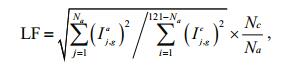 (1)
(1)where N a and Nc are the total numbers of wire electrodes with anodic and cathodic current values in WBE, respectively. Ij, ga and Ii, gc represent the galvanic values of the jth anodic and the ith cathodic wire electrodes, respectively. In the WBE, although the total of the anodic currents equals the cathodic currents, once localized corrosion occurs, the anodic regions may decrease with respect to the cathodic regions. Thus, LF is related closely to the anodic and cathodic densities, and the LF index could be used to characterize the degree of localized corrosion.
The LF values of three coating systems that were immersed in 3.5% NaCl solution for 100 d are plotted versus time in Fig. 8. The LF of Coating A increased rapidly and reached a maximum at the thirtieth dayand then decreased with time. The value remained at a higher level than Coatings B and C, which implies that the driving force for the local corrosion of Coating A was higher than the other two coating systems during the immersion. For Coating B, LF peaked at the 25th d and remained at a steady low value after 60 d. Local corrosion of the Coating B/WBE system transformed to uniform corrosion. This trend reflects that the local corrosion rate of Coating B was always lower than Coating A, higher than Coating C, and finally reached a very low level. For Coating C, LF increased slightly in the first 10 days, and then decreased and remained at a very low level until 100 days, which indicates that local corrosion of the Coating C/WBE system converted to uniform corrosion after 10 days and was maintained as such until the end. From the results, it can be concluded that coating systems with fibers and thiourea could inhibit localized corrosion of the scratched coating system and reduce the risk of local corrosion significantly.

|
| Figure 8 LF changes of the three coating systems with time |
SEM micrographs of the coating systems with 0.5 wt.% fibers and different thiourea concentrations after 120 d corrosion are shown in Fig. 9. For a thiourea content of 0.3 wt.%, after 120 d, almost no thiourea was adsorbed on the fiber surfaces as shown as Fig. 9b, which was similar to the surface state of the pure fiber as shown in Fig. 9a. This means that a small amount of thiourea was released gradually with time; the thiourea could not remain and adsorb on the fiber surface for a long time if the coating system was immersed in 3.5% NaCl solution. Therefore, a small amount of thiourea helped improve the self-healing abilityof the coating system for long-term durability. As the thiourea content increased to 0.7 wt.% (Fig. 9d), after a long immersion time, agglomerating thiourea remained packed on the fiber surface, which may affect the compactness of the coating and led to an unfavorable protection of the coating system. When the thiourea content was 0.5 wt.%, a high thiourea concentration resulted, which was evenly distributed on the fiber surface after a certain period (Fig. 9c). Thus, the coating system possessed a better protective ability, which indicates that glass fibers could be used as carriers for a certain amount of thiourea in the long term.

|
| Figure 9 SEM micrographs of coating systems with 0.5 wt.% fibers and different thiourea concentrations after 120 d of immersion a. 0 wt.%; b. 0.3 wt.%; c. 0.5 wt.%; d. 0.7 wt.%. |
To clarify the final corrosion products, the composition of products formed on the samples was determined by XRD and EDS. XRD patterns of the composite coatings are shown in Fig. 10, and the EDS patterns of the coating surfaces are shown in Fig. 11. The XRD results show the composition of corrosion products formed on Q235 carbon steel after 120-d immersion. The main products were γ-FeOOH, α-FeOOH, Fe3O4 and α-Fe2O3 (Han et al., 2014). The EDS pattern shows that the coating surface consisted mainly of Fe, O and Cl. Fe in the coating was from the Q235 substrate, whereas Cl and O were from the electrolyte. Element S was also visible as shown in Fig. 11b, which was believed to originate from thiourea. The comparative results prove that thiourea can be maintained for a relatively long time in the composite coating to serve as a protective assistant.

|
| Figure 10 XRD pattern of corrosion products formed on carbon steel after immersion for 120 d |

|
| Figure 11 EDS pattern of elemental distribution on different coating surfaces after immersion for 120 d a. Coating B; b. Coating C. |
Coating deterioration is a long process. To minimize the research period, scratched samples were used in this study. The main purpose was to verify whether glass fibers and thiourea could work together to provide long-term protection once the coating had been damaged. The results show that the addition of slender fibers and certain functional groups, such as thiourea, to the intermediate paint layer, can increase the long-term effects of the resultant coatings and allow for self-healing. When the coating surface was damaged, fibers that spread gradually to pitting sites of carbon steel and thiourea can be released slowly to the damaged site to form a thin film that inhibits corrosion. The EIS results show that the coating with 0.5 wt.% fibers and 0.5 wt.% thiourea presents improved corrosion protection and self-healing behavior on carbon-steel surfaces compared with other coating systems. Thiourea presented a longterm function because it can be absorbed on the fiber surface. XRD, EDS and SEM analyses confirmed the long-term protection and self-healing performance of the coating systems.
According to hard-soft-acid-base (HSAB) concepts (Welle et al., 1997), the '-NH2' group in the thiourea can function as a hard base. The carbon-steel surface that was immersed in the simulated seawater is usually covered with hard acidic iron oxide (Lin et al., 1999; Zhou et al., 2011). The amino groups of the thiourea adsorb on the electrode surface to form a protective layer and improve the energy barrier of the corrosion reaction as shown in Fig. 12. Thus, free migration of charges and corrosive ions is prevented on the electrode/solution interface (Abdel-Rehim et al., 2006; Fekry and Mohamed, 2010).

|
| Figure 12 Schematic diagram of the role of thiourea to protect the coating system |
Figure 13 shows a schematic diagram of the anticorrosion mechanism of the self-healing coating. For a scratched coating, fibers stretched out initially, and thiourea molecules were released rapidly into the scratched microenvironment through the fibers. Then, a thin film with high-barrier properties formed on the scratched substrate. The coating system that surrounded the scratched part was in good condition and played a good protective role at the initial immersion time, so the equivalent circuit had a parallel connection as shown in Fig. 13a. As water molecules and chloride ions penetrated longitudinally through the three-layer coating system into the interface of the coating/steel or laterally with defects entering the base metal, the perfect part of the coating was damaged by corrosive ions, and an electrochemical reaction was initiated on the interface of the coating/ steel. A competitive formation and dissolution process of the protective film formed by thiourea and fibers may result, so the film was not sufficiently compact to prevent the action of aggressive ions for a long time. Corrosion products appeared and accumulated on the carbon-steel surface, which affected the electrochemical process beneath the coating system, and so, the parameter that represents semi-infinite diffusion was introduced. The coating was damaged gradually and became detached partly from the base steel, which resulted in the decrease in protective ability of the coating system. Numerous tiny channels for corrosive ions in the coatings made it form in series with the double layer, so the equivalent circuit in Fig. 13b was used.

|
| Figure 13 Schematic representation of parts of the coated samples and the corresponding equivalent circuit elements, (a) early stage, (b) later stage |
Different classical polymer coating systems were prepared to prevent carbon-steel corrosion. Optimum additive quantities of fibers and thiourea were determined. The anticorrosion performance of the scratched-coating systems was evaluated by electrochemical and microscopic characterization.
1. The resistance of the scratched specimen with fibers and thiourea was higher than that of the blank coating over 120 d of immersion. A requirement of 0.5 wt.% fibers and 0.5 wt.% thiourea was necessary to achieve optimal long-term self-healing materials.
2. Fibers in the polymer coatings served as a carrier for thiourea. EDS and XRD results show that thiourea could adsorb on the fiber surfaces and could be retained for an extended period.
3. Fibers combined with thiourea could inhibit the local corrosion rate. Composite coatings with fibers and thiourea exhibit a good self-healing ability and the protection of carbon-steel surfaces.
| Abdel-Rehim S S, Khaled K F, Abd-Elshafi N S, 2006. Electrochemical frequency modulation as a new technique for monitoring corrosion inhibition of iron in acid media by new thiourea derivative. Electrochim. Acta, 51(16): 3269–3277. Doi: 10.1016/j.electacta.2005.09.018 |
| Almeida E C, Diniz A V, Trava-Airoldi V J, Ferreira N G, 2005. Electrochemical characterization of doped diamond-coated carbon fibers at different boron concentrations. Thin Solid Films, 485(1-2): 241–246. Doi: 10.1016/j.tsf.2005.03.053 |
| Balusamy T, Nishimura T, 2016. In-situ monitoring of the local corrosion process of scratched epoxy coated carbon steel in simulated pore solution containing varying percentage of chloride ions by localized electrochemical impedance spectroscopy. Electrochim. Acta, 199: 305–313. Doi: 10.1016/j.electacta.2016.02.034 |
| Blustein G, Di Sarli A R, Jaén J A, Romagnoli R, Del Amo B, 2007. Study of iron benzoate as a novel steel corrosion inhibitor pigment for protective paint films. Corros. Sci., 49(11): 4202–4231. Doi: 10.1016/j.corsci.2007.05.008 |
| Bonnel K, Le Pen C, Pébère N, 1999. E.I.S. characterization of protective coatings on aluminium alloys. Electrochim.Acta, 44(24): 4259–4267. Doi: 10.1016/S0013-4686(99)00141-3 |
| Campos I, Palomar-Pardavé M, Amador A, VillaVelázquez C, Hadad J, 2007. Corrosion behavior of boride layers evaluated by the EIS technique. Appl. Surf. Sci., 253(23): 9061–9066. Doi: 10.1016/j.apsusc.2007.05.016 |
| Chen B, Guizar-Sicairos M, Xiong G, Shemilt L, Diaz A, Nutter J, Burdet N, Huo S G, Mancuso J, Monteith A, Vergeer F, Burgess A, Robinson I, 2013. Threedimensional structure analysis and percolation properties of a barrier marine coating. Sci. Rep., 3: 1177. Doi: 10.1038/srep01177 |
| Chen S Q, Wang P, Zhang D, 2014. Corrosion behavior of copper under biofilm of sulfate-reducing bacteria. Corros.Sci., 87: 407–415. Doi: 10.1016/j.corsci.2014.07.001 |
| Cheng Y L, Zhang Z, Cao F H, Li J F, Zhang J Q, Wang J M, Cao C N, 2004. A study of the corrosion of aluminum alloy 2024-T3 under thin electrolyte layers. Corros. Sci., 46(7): 1649–1667. Doi: 10.1016/j.corsci.2003.10.005 |
| Conde A, de Damborenea J J, 2002. Electrochemical impedance spectroscopy for studying the degradation of enamel coatings. Corros. Sci., 44(7): 1555–1567. Doi: 10.1016/S0010-938X(01)00149-4 |
| Doherty M, Sykes J M, 2004. Micro-cells beneath organic lacquers:a study using scanning Kelvin probe and scanning acoustic microscopy. Corros. Sci., 46(5): 1265–1289. Doi: 10.1016/j.corsci.2003.09.016 |
| Ecco L G, Li J, Fedel M, Deflorian F, Pan J, 2014. EIS and in situ AFM study of barrier property and stability of waterborne and solventborne clear coats. Prog. Org.Coat., 77(3): 600–608. Doi: 10.1016/j.porgcoat.2013.11.024 |
| Fekry A M, Mohamed R R, 2010. Acetyl thiourea chitosan as an eco-friendly inhibitor for mild steel in sulphuric acid medium. Electrochim. Acta, 55(6): 1933–1939. Doi: 10.1016/j.electacta.2009.11.011 |
| Fouda A S, Soliman A H, 2015. Corrosion protection of carbon steel in hydrochloric acid solutions usingthiourea derivatives. Protection of Metals and Physical Chemistry of Surfaces, 51(5): 847–860. Doi: 10.1134/S2070205115050093 |
| Gergely A, Pászti Z, Hakkel O, Drotár E, Mihály J, Kálmán E, 2012. Corrosion protection of cold-rolled steel with alkyd paint coatings composited with submicron-structure typespolypyrrole-modified nano-size alumina and carbon nanotubes. Materials Science and Engineering:B, 177(18): 1571–1582. Doi: 10.1016/j.mseb.2012.03.049 |
| Gonçalves G S, Baldissera A F, Rodrigues L F Jr, Martini E M A, Ferreira C A, 2011. Alkyd coatings containing polyanilines for corrosion protection of mild steel. Synthetic Metals, 161(3-4): 313–323. Doi: 10.1016/j.synthmet.2010.11.043 |
| Han W, Pan C, Wang Z Y, Yu G C, 2014. A study on the initial corrosion behavior of carbon steel exposed to outdoor wet-dry cyclic condition. Corros. Sci., 88: 89–100. Doi: 10.1016/j.corsci.2014.07.031 |
| Jorcin J B, Aragon E, Merlatti C, Pébère N, 2006. Delaminated areas beneath organic coating:alocal electrochemical impedance approach. Corros. Sci., 48(7): 1779–1790. Doi: 10.1016/j.corsci.2005.05.031 |
| Karthik D, Tamilvendan D, Venkatesa Prabhu G, 2014. Study on the inhibition of mild steel corrosion by 1, 3-bis-(morpholin-4-yl-phenyl-methyl)-thiourea in hydrochloric acid medium. J. Saudi Chem. Soc., 18(6): 835–844. Doi: 10.1016/j.jscs.2011.10.009 |
| Lin J C, Chang S L, Lee S L, 1999. Corrosion inhibition of steel by thiourea and cations under incomplete cathodic protection in a 3.5% NaCl solution and seawater. J. Appl.Electrochem., 29(8): 911–918. Doi: 10.1023/A:1003533800038 |
| Pilbáth A, SzabóT, Telegdi J, Nyikos L, 2012. SECM study of steel corrosion under scratched microencapsulated epoxy resin. Prog. Org. Coat., 75(4): 480–485. Doi: 10.1016/j.porgcoat.2012.06.006 |
| Raps D, Hack T, Wehr J, Zheludkevich M L, Bastos A C, Ferreira M G S, Nuyken O, 2009. Electrochemical study of inhibitor-containing organic-inorganic hybrid coatings on AA2024. Corros. Sci., 51(5): 1012–1021. Doi: 10.1016/j.corsci.2009.02.018 |
| Saremi M, Yeganeh M, 2014. Application of mesoporous silica nanocontainers as smart host of corrosion inhibitor in polypyrrole coatings. Corros. Sci., 86: 159–170. Doi: 10.1016/j.corsci.2014.05.007 |
| Schneider O, Kelly R G, 2007. Localized coating failure of epoxy-coated aluminium alloy 2024-T3 in 0.5 M NaCl solutions:correlation between coatingdegradation, blister formation and local chemistry within blisters. Corros.Sci., 49(2): 594–619. Doi: 10.1016/j.corsci.2006.06.006 |
| Shao Y W, Jia C, Meng G Z, Zhang T, Wang F H, 2009. The role of a zinc phosphate pigment in the corrosion of scratched epoxy-coated steel. Corros. Sci., 51(2): 371–379. Doi: 10.1016/j.corsci.2008.11.015 |
| Shi W, Dong Z H, Kong D J, Guo X P, 2013. Application of wire beam electrode technique to investigate initiation and propagation of rebar corrosion. Cement Concrete Res., 48: 25–33. Doi: 10.1016/j.cemconres.2013.02.009 |
| Tan Y J, Aung N N, Liu T, 2006a. Novel corrosion experiments using the wire beam electrode.(Ⅰ) Studying electrochemical noise signatures from localized corrosion processes. Corros. Sci., 48(1): 23–38. Doi: 10.1016/j.corsci.2004.11.019 |
| Tan Y J, Liu T, Aung N N, 2006b. Novel corrosion experiments using the wire beam electrode:(Ⅲ) Measuring electrochemical corrosion parameters from both the metallic and electrolytic phases. Corros. Sci., 48(1): 53–66. Doi: 10.1016/j.corsci.2004.11.021 |
| Tan Y J, 1991. The effects of inhomogeneity in organic coatings on electrochemical measurements using a wire beam electrode:Part Ⅰ. Prog. Org. Coat., 19(1): 89–94. Doi: 10.1016/0033-0655(91)80013-9 |
| Thu Le Q, Bonnet G, Compere C, Trong Le H, Touzain S, 2005. Modified wire beam electrode:a useful tool to evaluate compatibility between organic coatings and cathodic protection. Prog. Org. Coat., 52(2): 118–125. Doi: 10.1016/j.porgcoat.2004.10.002 |
| Twite R L, Bierwagen G P, 1998. Review of alternatives to chromate for corrosion protection of aluminum aerospace alloys. Prog. Org. Coat., 33(2): 91–100. Doi: 10.1016/S0300-9440(98)00015-0 |
| Wang P, Zhang D, Qiu R, Wan Y, Wu J J, 2014. Green approach to fabrication of a super-hydrophobic film on copper and the consequent corrosion resistance. Corros. Sci., 80: 366–373. Doi: 10.1016/j.corsci.2013.11.055 |
| Wang T, Tan Y J, 2006. Understanding electrodeposition of polyaniline coatings for corrosion prevention applications using the wire beam electrode method. Corros. Sci., 48(8): 2274–2290. Doi: 10.1016/j.corsci.2005.07.012 |
| Welle A, Liao J D, Kaiser K, Grunze M, Mäder U, Blank N, 1997. Interactions of N, N'-dimethylaminoethanol with steel surfaces in alkaline and chlorine containing solutions. Appl. Surf. Sci., 119(3-4): 185–198. Doi: 10.1016/S0169-4332(97)00216-X |
| Yabuki A, Kawashima A, Fathona I W, 2014. Self-healing polymer coatings with cellulose nanofibers served as pathways for the release of a corrosion inhibitor. Corros.Sci., 85: 141–146. Doi: 10.1016/j.corsci.2014.04.010 |
| Yeganeh M, Keyvani A, 2016. The effect of mesoporous silica nanocontainers incorporation on the corrosion behavior of scratched polymer coatings. Prog.Org. Coat., 90: 296–303. Doi: 10.1016/j.porgcoat.2015.11.006 |
| Zhang B B, Zhao X, Li Y T, Hou B R, 2016. Fabrication of durable anticorrosion superhydrophobic surfaces on aluminum substrates via a facile one-step electrodeposition approach. RSC Adv., 6: 35455–35465. Doi: 10.1039/C6RA05484F |
| Zhang J T, Hu J M, Zhang J Q, Cao C N, 2004. Studies of impedance models and water transport behaviors of polypropylene coated metals in NaCl solution. Prog. Org.Coat., 49(4): 293–301. Doi: 10.1016/S0300-9440(03)00115-2 |
| Zhang K Y, Wang L D, Sun W, Liu G C, 2014. Corrosion inhibitor embedded spherical micro-pits fabricated using cetyltrimethyl ammonium bromide as etching template for self-healing corrosion protection. Corros. Sci., 88: 444–451. Doi: 10.1016/j.corsci.2014.08.001 |
| Zhao X, Liu S, Wang X T, Hou B R, 2014. Surface modification of ZrO2 nanoparticles with styrene coupling agent and its effect on the corrosion behaviour of epoxy coating. Chin.J. Oceanol. Limnol., 32(5): 1163–1171. Doi: 10.1007/s00343-014-3327-8 |
| Zhao X, Wang J, Wang Y H, Kong T, Zhong L, Zhang W, 2007. Analysis of deterioration process of organic protective coating using EIS assisted by SOM network. Electrochem.Commun., 9(6): 1394–1399. Doi: 10.1016/j.elecom.2007.01.049 |
| Zheludkevich M L, Poznyak S K, Rodrigues L M, Raps D, Hack T, Dick L F, Nunes T, Ferreira M G S, 2010. Active protection coatings with layered double hydroxide nanocontainers of corrosion inhibitor. Corros. Sci., 52(2): 602–611. Doi: 10.1016/j.corsci.2009.10.020 |
| Zhou X, Yang H Y, Wang F H, 2011. Corrosion Inhibition by Sorbitol/Diethylenetriamine Condensation Product for Carbon Steel in 3.5% NaCl Saturated Ca(OH)2 Solution. Acta Phys. Chim. Sin., 27(3): 647–654. |
| Zin I M, Lyon S B, Hussain A, 2005. Under-film corrosion of epoxy-coated galvanised steel:an EIS and SVET study of the effect of inhibition at defects. Prog. Org. Coat., 52(2): 126–135. Doi: 10.1016/j.porgcoat.2004.10.006 |