 2019, Vol. 37
Institute of Oceanology, Chinese Academy of Sciences
Article Information
- SUN Tianting, LIU Qingjun, WANG Dengting
- Stable-thickness study of masonry block on the inner slope of dikes
- Journal of Oceanology and Limnology, 37(6): 1921-1928
- http://dx.doi.org/10.1007/s00343-019-8235-5
Article History
- Received Sep. 7, 2018
- accepted in principle Dec. 21, 2018
- accepted for publication Jan. 29, 2019


2 Key Lab of Port, Waterway and Sedimentation Engineering of MOT, Nanjing 210024, China
Dikes are important coastal structures protecting human and infrastructures from flood and storm surge attacks. Damages to sea dikes would lead to major casualties and property losses. Sea dike engineering with large water depth, large wave height and long period, especially those built on low beaches, are high in wave run-ups. Thus, if the sea dikes are designed as not allowing overtopping, the crest elevation would be high, and the investment cost increases a lot as a result. Therefore, the sea dikes should be designed and calculated as allowing overtopping. However, when subject to storm surges, the overtopping discharge over the dike increases, bringing significant influence to the stability of revetment block stones and thus the stability of sea dikes. As a result, the inner slope protection is a focus of concern by all nations. Domestic and abroad scholars have researched overtopping streams on the inner slope. However, no formula has ever been proposed for the stable thickness of dry masonry block stone pitching on the inner slope. Design and Construction Specifications of Breakwater Dikes (JTS154-1-2011) from China has only provisions related to thickness of dry masonry block stone pitching on the seaward slope. Therefore, it is of significance to dike designs and inner dike protection that performs a quantitative analysis on stable thickness of block revetment on landward slope. For reasons listed above, systematic researches, in respect of domestic sea dike styles, are absolutely necessary against damages to inner slope of sea dikes subject to overtopping streams.
Since dry masonry block stones are widely applied to protection structures of inner slopes, this paper adopts dry masonry block stones in the physical model experiment as the pitching style of landward slope. Based on the experiment, the relation between the stable thickness of masonry block and the mean overtopping discharge is discussed, and a calculation formula of the stable thickness of masonry blocks is presented. The overtopping discharge obtained from the experiment is to go through calculation and analysis, and current domestic and abroad overtopping discharge formulas are put to comparison, for proposing an improved Hebsgaard formula of mean overtopping discharge.
1.1 Average overtopping-dischargeMany scholars have had researches on the mean overtopping discharge. Pullen et al. (2007) proposed overtopping formulas in EurOtop; Van der Meer and Bruce (2014) described new insights and design formulas on wave overtopping at sloped and vertical structures; Dodd (1998) presented a numerical model of wave run-up, overtopping and regeneration, which was based on the one-dimensional nonlinear shallow water equations; Etemad-Shahidi et al. (2016) derived formula for the prediction of wave overtopping rate at fully vertical and nearly vertical impermeable solid smooth structures by using scaling arguments and data mining approaches; Li et al. (2007) conducted physical model experiments on vertical dikes in respect of oblique waves, and proposed a mean overtopping discharge formula taking into consideration factors such as oblique angles. Several commonly used formulas for calculating overtopping discharges are listed below.
Owen (1980) from British proposed a formula of overtopping discharge occurring on the single-slope and multi-slope dikes. Expression (Eq.1) for average overtopping given by Owen is shown below:
 (1)
(1)wherein, Tm: a mean period of the wave incidence at the dike toe; A, B are empirical coefficients that differ between a single-slope dike and a sloping dike with shoulders.
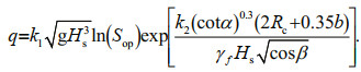
Empirical equations for average wave overtopping discharge have been developed by Hebsgaard et al. (1998) as the following.
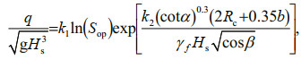 (2)
(2)wherein: q: overtopping discharge per unit structure length; Hs: significant wave height at the toe of the dike; Rc: crest elevation; Sop: deep water wave steepness obtained by the linear wave theory, Sop=2πHs/gTp2, Tp is spectral peak period; γf: influence coefficient of pitching layer roughness; β: oblique angle, which is of 90 degree when the wave incidence is normal to the dike axis; when a breast wall exists, k1 equals to -0.01, k2 equals to -1.0.
Van der Meer and Janssen (1995) from Dutch conducted systematic researches on overtopping discharge, and proposed an overtopping discharge formula adopted by many European countries.
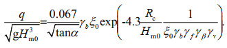 (3)
(3)The maximum of mean overtopping discharge is under control of the formula below:
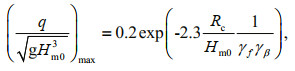 (4)
(4)wherein: α: angle between the front slope and the horizontal plane; γb: reduction coefficient used in the platform setup; ξ0: wave crushing coefficient, 
In the Code of Hydrology for Harbour and Waterway (JTS 145-2015) of China, provision of average overtopping equation is presented as the following.
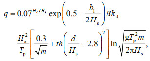 (5)
(5)wherein: q: overtopping discharge occurring in a unit width on top of the wave wall in a unit time; kA: influence coefficient of the pitching structure, which is related to the pitching structure style; B is empirical coefficient related to m.
1.2 Inner slope protectionMany scholars took in-depth researches on the damage progress of inner slopes, e.g. the flow speed and thickness of overtopping flow on the inner slope, and other parameters, in order to determine the inner slope protection method. Schüttrumpf and Oumeraci (2005) took researches on parameters of the overtopping flow in terms of experiments and theories; Pan et al. (2015) studied the overtopping erosion and failure mechanism of earthen levee strengthened by vegetated HPTRM system. Li et al. (2014) investigated the stability of articulated concrete block system during the combined wave and surge overtopping. Moreover, there is some laboratory study on stability of concrete slab on the inner slope of dikes under the coupling action of storm surge and wave conducted by Nanjing Hydraulic Research Institute in recent years.
Van Gent (1999) performed analysis in terms of the physical experimental model and mathematics model, and proposed a formula for calculating water body thickness and speed of the overtopping stream on the sea dike in the case of a single overtopping. The thickness and speed formula of the overtopping flow on the dike crest is shown below:
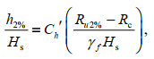 (6)
(6)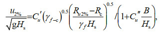 (7)
(7)wherein: γf–c: crest roughness coefficient; Ch′, Cu′, Cu′′: empirical coefficients, which are 0.1, 1.7, 0.1 respectively.
The thickness and speed formula of the overtopping water body on the inner slope is:
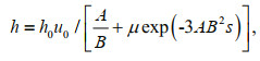 (8)
(8)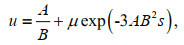 (9)
(9)wherein: s: horizontal ordinate along the inner slope, which is 0 at the junction of the crest with the inner slope; h0, u0 are thickness and speed of overtopping flow at the junction of the crest with the inner slope, which can be calculated from Eqs.6 and 7.
Hughes and Nadal (2009) comprehensively thought about waves and storm surges, and proposed, by the two-dimensional experiment, formulas of instantaneous overtopping discharge distribution, and overtopping stream speed and pressure, etc. The mean thickness and speed formula of the overtopping water body on the inner slope is as follow:
 (10)
(10)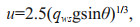 (11)
(11)wherein qws can be calculated from the following formula:
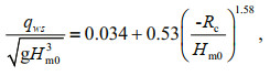 (12)
(12)wherein: qws: mean overtopping discharge when subject to waves and storm surges; θ: angle between the inner slope and the horizontal plane.
In conclusion, current research results are mainly about how to determine the protection standards of inner slopes by researches on inner slope overtopping stream parameters, but there is no calculation formula yet in the aspect of dry masonry block stone pitching thickness of inner slopes.
2 MODEL DESIGN AND EXPERIMENT METHOD 2.1 Experimental setupThe model experiment was conducted in Basic Sediment Theory Experiment Hall of the Nanjing Hydraulic Research Institute. The wave flume there is 175 m in length, 1.2 m in width, 1.5 m in height, generating a wave height up to 0.35 m and a wave period from 0.5 s to 6.0 s. A flat-push type of wavemaking paddle is adopted, which generating the maximum wave speed no less than 0.75 m/s. Computers control and generate desired wave elements automatically, and at the same time perform data acquisition and processing on water surface fluctuation signals detected by a wave-height gauge. This wave-generating device can deliver irregular waves of different spectral patterns as required by the experiment.
A water butt is adopted for water receiving and overtopping discharge measurement in this experiment. The water-receiving plate is 0.2 m in width.
2.2 Experimental methodA cross section of a simple single-slope dike is adopted in this model experiment. The seaward slope is 1:1.5, and the wave wall is vertical. Accropode blocks are adopted as the foreslope revetment. Dry masonry block stones are adopted as the inner slope revetment. Water depth at the front dike is 40 cm. The tested dike cross section is shown in Fig. 1 in modelscale units.

|
| Fig.1 Tested levee cross section (unit: mm) |
Different masonry block thicknesses and different wave periods are combined for a series of model experiments. For each combination, a small wave height is firstly used to act on the experiment cross section. Overtopping occurs when a wave run-up goes beyond the wave wall elevation and the overtopping impacts the dry masonry block stone pitching of the inner slope. If the masonry block is stable, the wave height increases further until the masonry block pitching loses stability and the corresponding mean overtopping discharge is determined then. The damage progress of the dry masonry block stone is observed. After each group of experiments, the masonry block pitching requires releveling. The experiment group includes:
(1) Wave period are respectively 1 s, 1.7 s, 2 s, and 3 s;
(2) Masonry block thickness adopts respectively 1.2 cm, 1.5 cm, 2.5 cm, and 3.5 cm;
(3) Waves are irregular waves which are simulated by JONSWAP spectrum;
(4) Protected slope are respectively 1, 1.5, 2, and 3.
Each group of experiments is repeated at least 3 times to avoid accidental factors and ensure the effectiveness of the experiment results.
2.3 Distinguish criterion of revetment block stabilityProvisions in the Code of Hydrology for Harbour and Waterway state that: The stability criterion of revetment blocks of slope-type structures subject to waves is represented by the tolerable instability n, i.e. an allowable percentage of those moved or fallen blocks, under wave impact, accounted for within a design wave height range above and below the still water level. For the dry masonry block stone pitching, if a block falls due to waves, bedding layers below the pitching would be affected by wave scour and erosion. Under waves for a long duration time, the revetment would be damaged further, thus influencing the entire stability of dikes. Therefore, it is believed in this paper that one block falling from the masonry block pitching indicates instability. It is noted in reference (Pan et al., 2005) that the condition, under which a dry masonry block stone subject to a certain wave element moves and is nearly to, but never, fall is defined as a critical stability.
3 EXPERIMENT RESULT AND ANALYSIS 3.1 Analysis of damage progress of inner slopeTo determine the relation between the stable thickness of inner slope masonry pitching and the wave height and wave period, each pitching thickness is combined with different wave heights and periods, and then the damage progresses of the inner slope masonry pitching are observed.
When a wave run-up went beyond the wave wall elevation, overtopping occurred over the wall. Under the overtopping, a few block stones of the dry masonry block stones slightly swung. When the wave height reached a critical wave height, several masonry blocks were tilted, and a slight deformation of inner slope could be observed horizontally from the vertical experiment cross section. However, due to the friction between dry masonry block stones around, the raised block stone did not fall at once (see Fig. 2). Affected by lasting waves, many block stones significantly projected, and several masonry blocks increasingly moved until fall. The overtopping kept scouring at the damaged location on the revetment, causing lots of block stones falling and finally a large-area instability of the inner slope revetment block stones occurred. In addition, it was found from observing the inner slope pitching that the first major place where the instability damage occurred was the inner crest of the wave wall, and the junction between the crest and the inner slope. This is because the overtopping goes beyond the overtopping wall and impacts the inner-wall crest due to gravity, causing the blocks of inner wave wall projecting, and thus resulting in the instability damage. In addition, the junction between the crest and the inner slope is poor at resisting a horizontal shearing force, therefore masonry blocks here are apt to be raised.

|
| Fig.2 The raised dry masonry block stones |
It is found during experiments that when the wave period keeps consistent, the thickness of masonry block pitching with the damage occurring increases as the wave height goes up. Therefore, changes of the wave steepness as a function of the thickness is put to analysis firstly, the relation between the two is drawn as in Fig. 3.

|
| Fig.3 Relative thickness versus wave steepness (m=1.5) |
At different wave periods, relative thicknesses increase as the wave steepness goes up. Seen from the above, the overtopping discharge increases as the wave steepness goes up. The larger the overtopping discharge is, the larger the force applied to the inner revetment, as well as the desired stable thickness. When period T=1.7 s, 2 s, 3 s, the relative thickness increases significantly as the wave steepness goes up. When T=1 s, the wave steepness increases to a large extent, but the relative thickness increases to a small extent as the wave steepness increases. It can be seen that when the period is long, the relative thickness of the masonry block is sensitive to the wave height change. As for a same relative thickness of the masonry block, the smaller the period turns, the larger the wave steepness corresponding to the critical instability of dry masonry block stones would be.
Conclusions above only deliver the qualitative relation between relative thickness of masonry block and the wave steepness, which is difficult to apply to practical engineering. In the case of a consistent wave period, as the wave steepness goes up, i.e. the wave height increases, the mean overtopping discharge increases gradually. Thus, to obtain a formula for masonry block pitching thickness of the inner slope, the thickness is turned to dimensionless; in order to further study the relation between the thickness and the dimensionless overtopping discharge. See Figs. 4 & 5.

|
| Fig.4 Relation between relative thickness and dimensionless average overtopping discharge (m=1.5) |

|
| Fig.5 Relation between relative thickness and dimensionless average overtopping discharge under different slopes |
Seen from Fig. 5, the relative thickness shows a linear trend with the dimensionless overtopping discharge. The relative thickness increases as the overtopping discharge increases, the formula is:
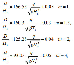 (13)
(13)wherein: D: stable thickness of inner slope masonry block pitching; Hs: significant wave height; q: mean overtopping discharge. The correlation coefficient is 0.93, which shows that the formula matches well with experiment results.
The Eq.13 presents a relation between the relative thickness and the mean overtopping discharge. However, in practical engineering, the mean overtopping discharge is difficult to obtain directly. Therefore a formula for calculating the mean overtopping discharge is necessary, in order to facilitate the direct application of the thickness formula of the inner slope masonry block pitching to dike engineering.
The measured overtopping discharge is put to dimensionless and comparison with Hebsgaard's formula, Van Der Meer's formula, and the formula in the Code of Hydrology for Harbour and Waterway. The comparison plot is shown below in Fig. 6.

|
| Fig.6 Comparison of measured and calculated values of overtopping discharge |
Analysis to the Fig. 6 above may lead to the following conclusions. In the case that the wave period keeps the same, the mean overtopping discharge of the sloping dike decreases as the relative free board turns larger. The practical value shows the same trend, which means that the experiment result is reasonable and effective. When T=1 s, 1.7 s, 2 s, Hebsgaard's formula is close to the experiment value, and when T=3 s, the experiment result is close to the result obtained by the Code of Hydrology for Harbour and Waterway. However, when T=1 s, 1.7 s, 2 s, the result obtained by the Code differs from the practical value, with the calculated value being larger. When T=1 s, various formulas differ greatly in results, but the calculated results of these formulas get close as the period increases. The Code of Hydrology for Harbour and Waterway result is always larger than the practical value, which means that the formula in the Code is conservative and relatively safe when used in designs.
The above formulas of abroad are mainly applicable to smaller overtopping discharge, whereas the overtopping discharge in this paper, is generally larger. Thus, there will be a certain deviation in the application by original formula. It is found by comprehensively comparing experiment results and calculated results of formulas above, Hebsgaard formula delivers results closer to practical values than the other two formulas. So Hebsgaard formula is slightly modified in order to be more applicable to dikes in China. Consequently, an improved Hebsgaard formula is proposed as follow:
 (14)
(14)In the case of breastwork, k1=-0.006 7, k2=-1.0, and the rest coefficients are the same as the Eq.2.
Calculated values of Eq.14 are compared with practical values, as seen as in Fig. 7. Seen from Fig. 7, a correlation coefficient between the calculated values by the formula of mean overtopping discharge and the practical values is 0.97. The calculated values by the improved Hebsgaard formula match well with the practical values, the former is generally larger than the latter, which makes the formula relatively safe.

|
| Fig.7 Verification of dimensionless average overtopping discharge |
In summary, the Eq.13 could be adopted to calculate the stable thickness of the inner slope masonry block pitching, wherein the mean overtopping discharge is calculated from the Eq.14.
Figure 8 compared the calculated masonry block thickness of the formulas and the experiment value for verification. Seen from Fig. 8, a correlation coefficient between the calculated values of thickness formula proposed herein of dry masonry block stones and the practical values is 0.91, showing that the calculated values match well with the experiment values. The equation presented herein may function as reference for inner slope protection of the dike.

|
| Fig.8 Verification of thickness of relative thickness |
In this paper, a series of physical model experiments were conducted for dry masonry block stone pitching of the inner slope subject to irregular waves. Under the irregular waves, the instability of masonry blocks is mainly due to the overtopping flow scour and erosion happening to the crest and the inner slope, causing the instability of the dike. The instability firstly happening to the inner slope mainly lies in the inner crest of the wave wall and the junction between the crest and the inner slope. In the inner dike protection, these two places should be paid attention to and properly reinforced. Domestic and abroad overtopping discharge formulas are put to comparison and analysis through overtopping discharge experiments, and as a result, in the case of irregular waves, improved Hebsgaard's formula is proposed. It shows that the overtopping discharge decreases as the relative free board goes up, and the calculated result matches the experiment result well. Through a series of experiments on the stability of masonry blocks, formulas for calculating masonry block thickness of inner slope subject to irregular waves are proposed. It is shown in experiments that the wave height is a direct factor deciding the masonry block thickness. The relative thickness shows a linear relation with the dimensionless overtopping discharge. The relative thickness is sensitive to the wave height change. Provided that the wave period is consistent, the relative thickness increases as the wave steepness increases. It is verified that the formula proposed herein for calculating the stable thickness is reasonable and effective.
Note that the formula proposed for the stable thickness of inner slope masonry blocks is specific to a certain cross section. Cases other than this type of cross section herein shall be evaluated through physical model experiments. The formula only takes the dry masonry block stone revetment into consideration. However, in real engineering, there are various styles of inner slope revetment. Corresponding model experiment researches shall be conducted on revetment styles such as riprap, concrete board, etc., rendering the formula more applicable and commonly used.
5 DADA AVAILABILITY STATEMENTThe datasets generated during and/or analyzed during the current study are available from the corresponding author on reasonable request.
6 ACKNOWLEDGEMENTThe laboratory experiments were conducted in Nanjing Hydraulic Research Institute. Thanks are extended to CHEN Weiqiu and ZHU Jialing, for their support of the experiments.
Dodd N. 1998. Numerical model of wave run-up, overtopping, and regeneration. Journal of Waterway, Port, Coastal, and Ocean Engineering, 124(2): 73-81.
DOI:10.1061/(ASCE)0733-950X(1998)124:2(73) |
Etemad-Shahidi A, Shaeri S, Jafari E. 2016. Prediction of wave overtopping at vertical structures. Coastal Engineering, 109: 42-52.
DOI:10.1016/j.coastaleng.2015.12.001 |
Hebsgaard M, Sloth P, Juhl J. 1998. Wave overtopping of rubble mound breakwaters. In: Proceedings of the 26th International Conference on Coastal Engineering. American Society of Civil Engineers, Copenhagen, Denmark, https://doi.org/10.1061/9780784404119.167.
|
Hughes S A, Nadal N C. 2009. Laboratory study of combined wave overtopping and storm surge overflow of a levee. Coastal Engineering, 56(3): 244-259.
DOI:10.1016/j.coastaleng.2008.09.005 |
Li L, Amini F, Pan Y, Li C. 2014. Stability monitoring of articulated concrete block strengthened levee in combined wave and surge overtopping conditions. In: Proceedings of Geo-Congress 2014. American Society of Civil Engineers, Atlanta, Georgia, https://doi.org/10.1061/9780784413272.026.
|
Li X L, Yu Y X, Zhao F Y, Lu G R. 2007. Experimental study on mean overtopping discharge of sloping seawall under oblique and multidirectional irregular waves. Acta Oceanologica Sinica, 29(1): 139-149.
(in Chinese with English abstract) DOI:10.3321/j.issn:0253-4193.2007.01.020 |
Owen M W. 1980. Design of Seawalls Allowing for Wave Overtopping. HR Wallingford, Wallingford, UK.
|
Pan J N, Wang D T, Wu M A, Yang Z J. 2005. Experimental study on stability of concrete block revetment under wave action. Journal of Hohai University (Natural Sciences), 33(4): 476-481.
(in Chinese with English abstract) DOI:10.3321/j.issn:1000-1980.2005.04.029 |
Pan Y, Li L, Amini F, Kuang C P. 2015. Overtopping erosion and failure mechanism of earthen levee strengthened by vegetated HPTRM system. Ocean Engineering, 96: 139-148.
DOI:10.1016/j.oceaneng.2014.12.012 |
Pullen T, Allsop N W H, Bruce T, Kortenhaus A, Schüttrumpf H, Van der Meer J W. 2007. EurOtop, European Overtopping Manual -Wave Overtopping of Sea Defences and Related Structures: Assessment Manual. Envrionment Agency, ENW, KFKI. 201p.
|
Schüttrumpf H, Oumeraci H. 2005. Layer thicknesses and velocities of wave overtopping flow at seadikes. Coastal Engineering, 52(6): 473-495.
DOI:10.1016/j.coastaleng.2005.02.002 |
Van der Meer J W, Bruce T. 2014. New physical insights and design formulas on wave overtopping at sloping and vertical structures. Journal of Waterway, Port, Coastal, and Ocean Engineering, 140(6): 04014025.
DOI:10.1061/(ASCE)WW.1943-5460.0000221 |
Van der Meer J W, Janssen W. 1995. Wave run-up and wave overtopping at dikes. In: Kobayashi N, Demirbilek Z eds. Wave Forces on Inclined and Vertical Wall Structures. American Society of Civil Engineers, New York. p.175-189.
|
Van Gent M R A. 1999. Physical Model Investigations on Coastal Structures with Shallow Foreshores: 2D Model Tests with Single and Double-peaked Wave Energy Spectra. Delft Hydraulics/Waterbouwkundig Laboratorium, Delft, The Netherlands.
|